Animal Drinking Troughs


If a premises has any form of mains water supply, including a back-up supply, then the water fittings regulations in England, Wales and Northern Irelandbyelaws in Scotland, apply. 

These legal requirements play an important role in protecting public health and safeguarding water supplies. Their purpose includes preventing the contamination and waste of water supplied by a water undertaker once it has entered a customer’s plumbing system.

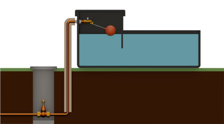
There are a number of key design requirements for troughs and animal drinking bowls including:

  • The trough/drinking bowl must be watertight

  • An inlet arrangement supplying water to the trough/drinking bowl must:

Be of an appropriate quality and standard to control the flow

Be rigidly and securely fixed

Be protected against environmental, accidental and animal damage

  • The supply to the trough/drinking bowl must be protected by a suitable form of fluid category 5 backflow protection.

The easiest way to prevent backflow from happening is to ensure a suitable gap is maintained between the water inlet feeding the trough or drinking bowl and the overflow or spill over level. Alternatively, where multiple troughs or drinking bowls are supplied from the same distribution pipe, a break tank arrangement fed via a Type AA, AB or AD arrangement could be used to provide backflow protection.

  • To minimise waste when maintaining or replacing components a servicing valve should be installed as close as practical to the inlet arrangement.

Stop valves which isolate trough(s)/drinking bowl(s) will also help to minimise waste in the event of a leak and enable pipework and troughs/drinking bowls not in use over the winter to be isolated and drained, which will help to prevent frost damage. Don’t forget to label which troughs/drinking bowls a stop valve controls.

  • All water fittings must be protected against environmental, accidental, and animal damage. For example, pipework laid at a depth less than 750 mm must be protected. This includes any above ground and outside the thermal envelop, which must be ducted, insulated and sealed. Sealing will help to prevent damage by rodents which is a common cause of leaks. In the case of troughs fitting a raised service box, which does not compromise any air gap providing backflow protection, will protect the inlet arrangement.

  • To stop the inlet from becoming submerged and prevent waste of water as a result of continuous spillage, troughs and drinking bowls should be installed level.

Related FAQs

What are the key design requirements for a trough or animal drinking bowl?

<h1 id="what-are-the-key-design-requirements">What are the key design requirements for a trough or animal drinking bowl?</h1><hr><h4 id="what-are-the-key-design-requirements"></h4><figure class="img-responsive" style="float: right; margin-bottom: 10px; margin-left: 10px; width: 330px; min-width: auto; min-height: auto;"><img src="/images/topics/faqs/good_trough_high_res_2d.jpg" class="img-responsive" style="width: 100%"></figure><p>There are a number of design requirements for troughs and animal drinking bowls including:</p><ul><li><p>The trough/drinking bowl must be watertight</p></li></ul><ul><li><p>An inlet arrangement supplying water to the trough/drinking bowl must:</p></li></ul><p style="margin-left:60px;">Be of an appropriate quality and standard to control the flow</p><p style="margin-left:60px;">Be rigidly and securely fixed</p><p style="margin-left:60px;">Be protected against environmental, accidental and animal damage</p><ul><li><p>The supply to the trough/drinking bowl must be protected by a suitable form of fluid category 5 backflow protection.</p></li></ul><p style="margin-left:40px;">The easiest way to prevent backflow from happening is to ensure a suitable gap is maintained between the water inlet feeding the trough or drinking bowl and the overflow or spill over level. Alternatively, where multiple troughs or drinking bowls are supplied from the same distribution pipe, a break tank arrangement fed via a Type AA, AB or AD arrangement could be used to provide backflow protection.</p><ul><li><p>To minimise waste when maintaining or replacing components a servicing valve should be installed as close as practical to the inlet arrangement.</p></li></ul><p style="margin-left:40px;">Stop valves which isolate trough(s)/drinking bowl(s) will also help to minimise waste in the event of a leak and enable pipework and troughs/drinking bowls not in use over the winter to be isolated and drained, which will help to prevent frost damage. Don’t forget to label which troughs/drinking bowls a stop valve controls.</p><ul><li><p>All water fittings must be protected against environmental, accidental, and animal damage . For example, pipework laid at a depth less than 750 mm must be protected. This includes any above ground and outside the thermal envelop, which must be ducted, insulated and sealed. Sealing will help to prevent damage by rodents which is a common cause of leaks. In the case of troughs fitting a raised service box, which does not compromise any air gap providing backflow protection, will protect the inlet arrangement.</p></li></ul><ul><li><p>To stop the inlet from becoming submerged and prevent waste of water as a result of continuous spillage, troughs and drinking bowls should be installed level.</p><p><br></p></li></ul><h4 id="additional-sources-of-information">Additional sources of information</h4><ul><li><p><a href="/downloads/public_area/guidance/publications/general/april_2023/guidance_2024/booklets/agricultural_booklet__v1.2_feb_2024.pdf" target="_blank">Agricultural booklet</a></p></li></ul><p>&nbsp;</p><p>&nbsp;</p><!--PARTBREAK--><h1 id="topics">FAQs</h1><!--PARTBREAK--><p><br></p>

Type AB air gaps

<h1 id="type-ab-air-gaps">Type AB air gaps</h1><hr><p>A Type AB air gap is a non-mechanical backflow prevention arrangement comprising of an inlet which discharges water into a cistern, vessel, fitting or appliance (receiving vessel) fitted with an outlet and a rectangular weir or ‘slot’ overflow. Depending on the outcome of an assessment by the local water undertaker it can feed a single or multiple installations.</p><p style="text-align: start;">A Type AB air gap is rated by the Regulators as suitable backflow protection against both back siphonage and back pressure at the highest level of contamination risk,&nbsp;fluid category&nbsp;5.</p><figure class="img-responsive" style="min-width: auto; min-height: auto; float: none; margin-left: auto; margin-right: auto; width: 400px;"><img src="/images/topics/backflow/15-type-ab_with_ss_.png" style="width: 100%"></figure><p>A summary of some of the key requirements applicable to a Type AB air gap is given below:</p><ol><li><p>The air gap is an unobstructed and complete physical break between the lowest point of discharge and the critical water level of the weir overflow. Measured vertically it must be no less than 20 mm or twice the internal diameter of the supply whichever is the greater.</p></li><li><p>The critical level (sometimes referred to as h) is the fluid level in the receiving vessel under fault conditions i.e. when the outlet is closed but the inlet continues to discharge. It is measured at least 2 seconds after closing the water inlet</p></li><li><p>Whether sited internally or externally (as shown in the diagram opposite) the weir overflow must be rectangular (non-circular) and capable of accommodating discharge under fault conditions. Where a screened mesh is installed consideration should be given to the impact this may have on discharge flow. The air gap can be confirmed by test or calculation using the Type AB air gap&nbsp;<a href="https://www.waterregsuk.co.uk/information/tools">calculator.</a></p></li><li><p>Neither the fluid pathway to the overflow nor the discharge from it should be&nbsp;<a href="https://www.waterregsuk.co.uk/guidance/backflow-protection/backflow-protection/backflow-protection1/what-is-an-unrestric/">restricted</a>. For example, there should be a sufficient gap between the overflow and any surface to accommodate full discharge unimpeded during fault conditions.</p></li><li><p>Submerged supply pipes are not permitted. If the supply pipe feeding the inlet or the inlet itself comes into contact with the contents of the receiving vessel, for example due to splashing or foaming, then the air gap is considered to be compromised and must be increased to the point no contact occurs.</p></li><li><p>Type AB air gap installations, including screened mesh, should be inspected, cleaned and as necessary maintained every 6 months (BS EN 806: 5)</p></li></ol><p><br></p><viewer-3d style="box-sizing: border-box; font-family: -apple-system, system-ui, BlinkMacSystemFont, &quot;Segoe UI&quot;, Roboto, &quot;Helvetica Neue&quot;, Arial, sans-serif;"><div class="block svelte-1wjbz9j"><div class="container svelte-1uqz219"></div></div></viewer-3d><div><div class="duoEditArea"><p><br></p></div></div><p><br></p><p><br></p><p><br></p><p><br></p><!--PARTBREAK--><h1 id="faqs">FAQs</h1><!--PARTBREAK--><p><br></p>

What is a Type AB air gap?

<h1 id="backflow-protection-faqs">What is a Type AB air gap?</h1><hr><h4 id="what-is-a-type-ab-air"></h4><p>A Type AB air gap is a non-mechanical backflow prevention arrangement comprising of an inlet, receiving vessel and unrestricted weir overflow (rectangular or non-circular). To be considered as providing fluid category 5 backflow protection there must be an air gap of no less than 20 mm or twice the diameter of the supply whichever is the greatest, between the lowest point water discharges from the inlet and what is called the critical water level (also referred to as 'h'). The critical water level being the level reached in any part of the receiving vessel, including above the spill over level from the overflow, two seconds after the maximum water flow has ceased.</p><p><strong>Please note:</strong><br>If the supply pipe feeding the inlet or the inlet itself comes into contact with the contents of the receiving vessel, for example due to splashing or foaming, then the air gap is considered to be compromised and must be increased.</p><p>During fault conditions the water pathway to the overflow and discharge from the overflow itself must not be restricted. For example, there should be a sufficient gap between the overflow and any surface to accommodate full discharge unimpeded.</p><viewer-3d><figure class="img-responsive" style="min-width: auto; min-height: auto;"><img src="/images/guidance-2023/backflow/air-gap.png" class="img-responsive" style="width: 100%"></figure></viewer-3d><!--PARTBREAK--><h1 id="topics">FAQs</h1><!--PARTBREAK--><p><br></p>

What is an unrestricted discharge from a Type AB air gap?

<h1 id="what-is-an-unrestricted-discharge-from">What is an unrestricted discharge from a Type AB air gap?</h1><hr><p>To be considered as providing fluid category 5 backflow protection, in addition to maintaining a suitable air gap, the water pathway to a Type AB air gap overflow, and discharge from the weir itself, must be unrestricted.</p><p>If the overflow is located close to another surface, such as a wall or other installation behind, in front or below the overflow, the gap between the discharge point and these surfaces must be sufficient to accommodate full discharge unimpeded. One way to demonstrate this is to ensure there is a clearance equivalent in shape and size to the weir overflow which is maintained to the air break to drain or floor level.</p><figure class="img-responsive" style="min-width: auto; min-height: auto;"><img src="/images/topics/faqs/16-1ab-guidance23-v4a-small.png" class="img-responsive" style="width: 100%"></figure><p>&nbsp;</p><p>&nbsp;</p><!--PARTBREAK--><h1 id="topics">FAQs</h1><!--PARTBREAK--><p><br></p>

Regulations & Byelaws which apply include but are not limited to:


  • Regulation 3 England & Wales

  • Regulation 3 Northern Ireland 

  • Byelaw 3 Scotland 

  • Regulation 4 England & Wales

  • Regulation 4 Northern Ireland 

  • Byelaw 4 Scotland 

  • Regulation 5 England & Wales

  • Regulation 5 Northern Ireland 

  • Byelaw 5 Scotland 

  • Schedule 2 paragraph 2

  • Schedule 2 paragraph 3

  • Schedule 2 paragraph 4

  • Schedule 2 paragraph 5

  • Schedule 2 paragraph 6

  • Schedule 2 paragraph 7

  • Schedule 2 paragraph 8

  • Schedule 2 paragraph 10

  • Schedule 2 paragraph 11

  • Schedule 2 paragraph 15

  • Schedule 2 paragraph 30


  • Regulation 5 England & Wales

  • Regulation 5 Northern Ireland

  • Byelaw 5 Scotland

  • Schedule 2 paragraph 2

  • Schedule 2 paragraph 3

  • Schedule 2 paragraph 4

  • Schedule 2 paragraph 7

  • Schedule 2 paragraph  8

  • Schedule 2 paragraph 11

  • Schedule 2 paragraph 15


Publications


  • Agricultural booklet

  • Regulators' Specification for backflow

  • Regulation 4(1)(a) compliance guidance

  • Regulation 4(1)(a) guidance: BS 6920 compliance overview

  • Full list


Back to all Topics


We use cookies to give you the best possible experience with Water Regs UK. Some are essential to provide website functions and ensure the website is secure. We also use cookies to help us understand how people use the site and to make improvements. Click "Accept All" to enable recommended settings or click "Manage cookies" to adjust your settings. For more details, see our Cookie Policy.