Backflow Protection 


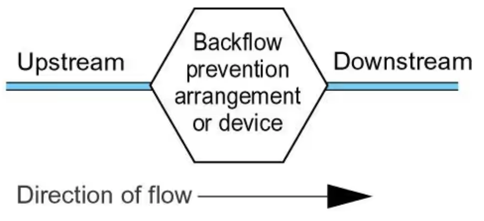
For the purposes of the water fittings regulations in England, Wales and Northern Irelandbyelaws in Scotland, backflow occurs when fluid flows in the opposite to the intended or normal direction of flow. 

There are two types of backflow, back pressure and back siphonage. 

The circumstances which could lead to backflow are a common occurrence across the UK, contamination of public water supplies by backflow of fluids from customers premises is not theoretical. It is an ever present threat to water quality and public health.

Good design and the installation of suitable backflow prevention arrangements are key to avoiding backflow, which is why notification is so important.

Schedule 2 paragraph 15 of the water fittings regulations in England, Wales and Northern Irelandbyelaws in Scotland require every plumbing system to incorporate protection against backflow. This is often referred to as point of use backflow protection. It can be provided by an air or tap gap arrangement or a mechanical backflow prevention device. 

Backflow prevention arrangements and devices permitted under the regulations/byelaws need to be approved by the regulator  or alternatively authorised as a relaxation. Relaxations allow a water undertaker the discretion to accept an arrangement as preventing backflow. 

Wherever practicable plumbing systems should be protected against backflow without the necessity to rely on mechanical backflow protection devices.

Related FAQs

When does schedule 2 paragraph 2 not apply?

<h1 id="when-does-schedule-2-paragraph-2">When does schedule 2 paragraph 2 not apply?</h1><hr><h4 id="when-does-schedule-2-paragraph-2"></h4><p>Providing appropriate and adequate backflow protection against the highest level of risk downstream is installed, an installation not used to supply water for drinking, bathing, food preparation or cooking purposes is exempt from complying with schedule 2 paragraph 2(1). <br></p><p>Please note the backflow protection required needs to be assessed by the local water undertaker and other requirements of the water fittings regulations/byelaws continue to apply.</p><p>&nbsp;</p><p>&nbsp;</p><!--PARTBREAK--><h1 id="topics">FAQs</h1><!--PARTBREAK--><p><br></p>

What is backflow?

<h1 id="backflow-protection-faqs">What is backflow?</h1><hr><h4 class="p1" id="what-is-backflow"></h4><p class="p1">Backflow occurs when fluid flows in the opposite to the intended or normal direction of flow. There are two types of backflow, back pressure and back siphonage.</p><figure class="img-responsive" style="width: 340px; float: none; margin-left: auto; margin-right: auto; min-width: auto; min-height: auto;"><img src="/images/topics/faqs/flow-normal__pipes__v2.png" class="img-responsive" style="width: 100%"></figure><p>&nbsp;</p><ul><li><p>Backpressure: occurs when the pressure downstream increases above that of the supply pressure, in effect pushing fluids backwards against the intended or normal direction of flow.</p></li></ul><p>&nbsp;<img src="/images/topics/faqs/flow-backpressure__pipes_.png" class="img-responsive" style="display:block;float:none;margin-left:auto;margin-right:auto;width:318px" loading="lazy"></p><ul><li><p>Back siphonage: occurs when the supply pressure drops below that of the system it is supplying creating a depressurisation or vacuum which pulls fluids backwards against the intended or normal direction of flow.</p></li></ul><p>&nbsp;<img src="/images/topics/faqs/flow-back_siphonage__pipes_.png" class="img-responsive" style="width:318px;display:block;float:none;margin-left:auto;margin-right:auto" loading="lazy"></p><p class="p1">The type of backflow risk is dependent upon a number of factors. Good design and the installation of suitable backflow prevention arrangements are key to avoiding backflow, which is why&nbsp;notification&nbsp;is so important.</p><p class="p1">As the circumstances which could lead to backflow are a common occurrence across the UK, contamination of public water supplies by backflow of fluids from customers premises is not theoretical. It is an ever present threat to water quality and public health.</p><p class="p1">As there have been a number of serious contamination events across the UK water undertakers take their role in preventing such incidents very seriously. Where infringements are suspected or identified they will act, not only to protect water quality and public health, but also to support owners and occupiers of premises to meet their legal obligations.</p><p class="p1">Where contamination incidents occur, it is likely that enforcement action, including criminal proceedings, will be taken against those who fail to meet their legal obligations.</p><p>&nbsp;</p><!--PARTBREAK--><h1 id="topics">FAQs</h1><!--PARTBREAK--><p><br></p>

What is contamination?

<h1 id="backflow-protection-faqs">What is contamination?</h1><hr><h4 class="p1" id="what-is-contamination"></h4><p class="p1">Water undertakers are legally required to ensure the drinking water they supply is wholesome. Contamination occurs when there is a change in water quality irrespective of whether or not it is harmful to health</p><p>&nbsp;</p><p>&nbsp;</p><p>&nbsp;</p><!--PARTBREAK--><h1 id="topics">FAQs</h1><!--PARTBREAK--><p><br></p>

What is a fluid category?

<h1 id="what-is-a-fluid-category">What is a fluid category?</h1><hr><h4 class="p1" id="what-is-a-fluid-category"></h4><p>Schedule 1 of the water fittings regulations in&nbsp;<a href="https://www.legislation.gov.uk/uksi/1999/1148/contents/made">England, Wales</a>&nbsp;and&nbsp;<a href="https://www.legislation.gov.uk/nisr/2009/255/contents/made">Northern Ireland</a>,&nbsp;<a href="https://www.scottishwater.co.uk/-/media/ScottishWater/Document-Hub/Business-and-Developers/Byelaws-and-Trade-Effluent/170718swbyelawsexplained.pdf">byelaws in Scotland</a>, classify the health risk posed by potential contaminants using a scale called fluid categories.&nbsp;</p><p class="p2">There are five fluid categories in total the lowest being 1 no risk the highest 5 a serious health hazard.&nbsp;</p><figure class="img-responsive" style="width: 621px; float: none; margin-left: auto; margin-right: auto; min-width: auto; min-height: auto;"><img src="/images/topics/faqs/screenshot_2023-02-21_at_12.43.00.png" class="img-responsive" style="width: 100%"></figure><p>&nbsp;</p><p>&nbsp;</p><div class="duoactiveblock"><div class="tablewrapper"><table class="t1 table table-bordered table-striped table-responsive"><tbody><tr><td class="duosubcell"><h4 class="p2" id="fluid-category">Fluid Category&nbsp;</h4></td><td class="duosubcell"><h4 class="p2" id="description">Description</h4></td><td class="duosubcell"><h4 class="p2" id="example">Example&nbsp;</h4></td></tr><tr><td class="duosubcell"><p>&nbsp;</p><div><p>1</p></div><p>&nbsp;</p></td><td class="duosubcell"><p>&nbsp;</p><div><p>Wholesome (drinking) water supplied by the undertaker</p></div><p>&nbsp;</p></td><td class="duosubcell"><p>&nbsp;</p><div><p>water direct from a water undertaker’s main</p></div><p>&nbsp;</p></td></tr><tr><td class="duosubcell"><p>&nbsp;</p><div><p>2</p></div><p>&nbsp;</p></td><td class="duosubcell"><p>&nbsp;</p><div><p>Wholesome (drinking) water which has been changed either heated or altered in taste, odour or appearance &nbsp;</p></div><p>&nbsp;</p></td><td class="duosubcell"><p>&nbsp;</p><div><p>Hot water&nbsp;</p></div><p>&nbsp;</p></td></tr><tr><td class="duosubcell"><p>&nbsp;</p><div><p>3</p></div><p>&nbsp;</p></td><td class="duosubcell"><p>&nbsp;</p><div><p>Fluids posing a slight health hazard</p></div><p>&nbsp;</p></td><td class="duosubcell"><p>&nbsp;</p><div><p>low toxicity chemicals such as common disinfectants</p></div><p>&nbsp;</p></td></tr><tr><td class="duosubcell"><p>&nbsp;</p><div><p>4</p></div><p>&nbsp;</p></td><td class="duosubcell"><p>&nbsp;</p><div><p>Fluids posing a significant health hazard.</p></div><p>&nbsp;</p></td><td class="duosubcell"><p>&nbsp;</p><div><p>Toxic substances such as pesticides and environmental organisms</p></div><p>&nbsp;</p></td></tr><tr><td class="duosubcell"><p>&nbsp;</p><div><p>5</p></div><p>&nbsp;</p></td><td class="duosubcell"><p>&nbsp;</p><div><p>Fluids posing a serious health hazard</p></div><p>&nbsp;</p></td><td class="duosubcell"><p>&nbsp;</p><div><p>Pathogenic organisms, radioactive or very toxic substances such as faecal matter</p></div><p>&nbsp;</p></td></tr></tbody></table></div></div><p><br><br></p><p>&nbsp;</p><!--PARTBREAK--><h1 id="topics">FAQs</h1><!--PARTBREAK--><p><br></p>

Who assess backflow risks?

<h1 id="who-assess-backflow-risks">Who assess backflow risks?</h1><hr><h4 id="who-assess-backflow-risks"></h4><p>As part of their statutory duty to enforce the water fittings regulations in <a href="https://www.legislation.gov.uk/uksi/1999/1148/contents/made">England, Wales</a> and <a href="https://www.legislation.gov.uk/nisr/2009/255/contents/made">Northern Ireland</a>, <a href="https://www.scottishwater.co.uk/-/media/ScottishWater/Document-Hub/Business-and-Developers/Byelaws-and-Trade-Effluent/170718swbyelawsexplained.pdf">byelaws in Scotland</a>, the local water undertaker will identify the level of backflow protection needed. This categorisation will be based on a number of factors including the highest downstream fluid category risk the fitting is or is likely to be subject.</p><p>&nbsp;</p><!--PARTBREAK--><h1 id="topics">FAQs</h1><!--PARTBREAK--><p><br></p>

What is a backflow prevention arrangement or device?

<h1 id="what-is-a-backflow-prevention-arrangement">What is a backflow prevention arrangement or device?</h1><hr><h4 class="p1" id="a-backflow-prevention-arrangement-or-device"></h4><p class="p1">It is in effect a barrier intended to prevent contaminated fluid flowing backwards.</p><figure class="img-responsive" style="float: left; width: 450px; margin-right: 10px; margin-left: 10px; min-width: auto; min-height: auto;"><img src="/images/topics/backflow_protection.png" style="width: 100%"></figure><p class="p1"><br></p><p><br></p><p><br></p><p><br></p><p><br></p><p class="p1"><a href="https://www.legislation.gov.uk/uksi/1999/1148/schedule/2/paragraph/15">Schedule 2 paragraph 15</a>&nbsp;of the water fittings regulations in&nbsp;<a href="https://www.legislation.gov.uk/uksi/1999/1148/contents/made">England, Wales</a>&nbsp;and&nbsp;<a href="https://www.legislation.gov.uk/nisr/2009/255/contents/made">Northern Ireland</a>,&nbsp;<a href="https://www.scottishwater.co.uk/-/media/ScottishWater/Document-Hub/Business-and-Developers/Byelaws-and-Trade-Effluent/170718swbyelawsexplained.pdf">byelaws in Scotland</a>&nbsp;require every plumbing system to incorporate protection against backflow. This is often referred to as point of use backflow protection. It can be provided by an&nbsp;air or tap gap arrangement or a mechanical backflow prevention device.&nbsp;</p><p class="p1">Backflow prevention arrangements and devices permitted under the regulations/byelaws need to be approved by the&nbsp;regulator&nbsp; or alternatively authorised as a relaxation. Relaxations allow a water undertaker the discretion to accept an arrangement as preventing backflow.&nbsp;</p><p class="p1">The regulator rates a backflow protection arrangement or device for suitability against contamination risk (fluid categories) and types of backflow risk - back siphonage or back pressure. They should always be accessible for inspection, maintenance and replacement.</p><figure class="img-responsive" style="float: left; margin-right: 20px; margin-bottom: 20px; width: 181px; min-width: auto; min-height: auto;"><img src="/images/topics/faqs/7-6-cr_dcv__1_.png" class="img-responsive" style="width: 100%"></figure><p>Backflow prevention devices, are required to be corrosion resistant. For example, for metallic backflow prevention devices manufactured of gunmetal or other dezincification resistant materials. Dezincification water fittings are typically marked with a CR symbol.</p><p>Wherever practicable plumbing systems should be protected against backflow without the necessity to rely on mechanical backflow protection devices.</p><p>&nbsp;</p><p>&nbsp;</p><!--PARTBREAK--><h1 id="topics">FAQs</h1><!--PARTBREAK--><p><br></p>

Type AA air gaps

<h1 id="type-aa-air-gaps">Type AA air gaps</h1><hr><p>A Type AA air gap is a non-mechanical backflow prevention arrangement comprising of an inlet which discharges water into a cistern, vessel, fitting or appliance (receiving vessel) and an outlet. Depending on the outcome of an assessment by the local water undertaker it can feed a single or multiple installations.</p><p style="text-align: start;">A Type AA air gap is rated by the Regulators as suitable backflow protection against both back siphonage and back pressure at the highest level of contamination risk,&nbsp;fluid category&nbsp;5.</p><figure class="img-responsive" style="float: none; margin-left: auto; margin-right: auto; width: 400px;"><img src="/images/topics/backflow/15-type-aa_with_ss_.png" style="width: 100%"></figure><p><br></p><p>A summary of some of the key requirements for a Type AA air gap is given below:</p><ol><li><p>The supply pipe and inlet control must be external to the receiving vessel and fixed so the air gap is maintained and unrestricted.</p></li><li><p>The air gap is an unobstructed and complete physical break between the lowest point of discharge and the spillover level of the contents of the receiving vessel. Measured vertically it must be no less than 20 mm or twice the internal diameter of the supply whichever is the greater.</p></li><li><p>The spillover level is the level at which the contents of receiving vessel spill over the top edge when the inflow of water exceeds the outflow through the outlet i.e. demand.</p></li><li><p>The spillover is unrestricted.</p></li><li><p>If the supply pipe feeding the inlet or the inlet itself comes into contact with the contents of the receiving vessel, for example due to splashing or foaming, then the air gap is considered to be compromised and must be increased to the point no contact occurs.</p></li><li><p>Type AA air gaps should be inspected, and as necessary, maintained every 6 months (BS EN 806: 5)</p></li></ol><p><br></p><p><br></p><!--PARTBREAK--><h1 id="faqs">FAQs</h1><!--PARTBREAK--><p><br></p>

Type AB air gaps

<h1 id="type-ab-air-gaps">Type AB air gaps</h1><hr><p>A Type AB air gap is a non-mechanical backflow prevention arrangement comprising of an inlet which discharges water into a cistern, vessel, fitting or appliance (receiving vessel) fitted with an outlet and a rectangular weir or ‘slot’ overflow. Depending on the outcome of an assessment by the local water undertaker it can feed a single or multiple installations.</p><p style="text-align: start;">A Type AB air gap is rated by the Regulators as suitable backflow protection against both back siphonage and back pressure at the highest level of contamination risk,&nbsp;fluid category&nbsp;5.</p><figure class="img-responsive" style="min-width: auto; min-height: auto; float: none; margin-left: auto; margin-right: auto; width: 400px;"><img src="/images/topics/backflow/15-type-ab_with_ss_.png" style="width: 100%"></figure><p>A summary of some of the key requirements applicable to a Type AB air gap is given below:</p><ol><li><p>The air gap is an unobstructed and complete physical break between the lowest point of discharge and the critical water level of the weir overflow. Measured vertically it must be no less than 20 mm or twice the internal diameter of the supply whichever is the greater.</p></li><li><p>The critical level (sometimes referred to as h) is the fluid level in the receiving vessel under fault conditions i.e. when the outlet is closed but the inlet continues to discharge. It is measured at least 2 seconds after closing the water inlet</p></li><li><p>Whether sited internally or externally (as shown in the diagram opposite) the weir overflow must be rectangular (non-circular) and capable of accommodating discharge under fault conditions. Where a screened mesh is installed consideration should be given to the impact this may have on discharge flow. The air gap can be confirmed by test or calculation using the Type AB air gap&nbsp;<a href="https://www.waterregsuk.co.uk/information/tools">calculator.</a></p></li><li><p>Neither the fluid pathway to the overflow nor the discharge from it should be&nbsp;<a href="https://www.waterregsuk.co.uk/guidance/backflow-protection/backflow-protection/backflow-protection1/what-is-an-unrestric/">restricted</a>. For example, there should be a sufficient gap between the overflow and any surface to accommodate full discharge unimpeded during fault conditions.</p></li><li><p>Submerged supply pipes are not permitted. If the supply pipe feeding the inlet or the inlet itself comes into contact with the contents of the receiving vessel, for example due to splashing or foaming, then the air gap is considered to be compromised and must be increased to the point no contact occurs.</p></li><li><p>Type AB air gap installations, including screened mesh, should be inspected, cleaned and as necessary maintained every 6 months (BS EN 806: 5)</p></li></ol><p><br></p><viewer-3d style="box-sizing: border-box; font-family: -apple-system, system-ui, BlinkMacSystemFont, &quot;Segoe UI&quot;, Roboto, &quot;Helvetica Neue&quot;, Arial, sans-serif;"><div class="block svelte-1wjbz9j"><div class="container svelte-1uqz219"></div></div></viewer-3d><div><div class="duoEditArea"><p><br></p></div></div><p><br></p><p><br></p><p><br></p><p><br></p><!--PARTBREAK--><h1 id="faqs">FAQs</h1><!--PARTBREAK--><p><br></p>

Type AC air gaps

<h1 id="type-ac-air-gaps">Type AC air gaps</h1><hr><p>A Type AC air gap is a non-mechanical backflow prevention arrangement comprising of a vented, but submerged inlet that discharges into a cistern, vessel, fitting or appliance fitted (receiving vessel) with an outlet and circular overflow.</p><p style="text-align: start;">A Type AC air gap is rated by the Regulators as suitable backflow protection against both back siphonage and back pressure for contamination risks no greater than&nbsp;fluid category&nbsp;3 .</p><figure class="img-responsive" style="float: none; margin-left: auto; margin-right: auto; width: 400px; min-width: auto; min-height: auto;"><img src="/images/topics/backflow/15-type-ac_with_ss_.png" style="width: 100%"></figure><p>A summary of some of the key requirements applicable to a Type AC air gap is given below:</p><ol><li><p>The air gap is an unobstructed and complete physical break between the lowest point of the vent (air inlet) and the critical water level of the weir overflow. It must be no less than 20 mm or twice the internal diameter of the supply whichever is the greater.</p></li><li><p>The critical level is the fluid level in the receiving vessel under fault conditions i.e. when the outlet is closed but the inlet continues to discharge. It is measured at least 2 seconds after closing the water inlet.</p></li><li><p>Supply pipes maybe submerged but adjustable or dismantlable joints on the are not permitted below the critical water level.</p></li><li><p>The overflow shall be not less than 19mm (internal diameter).</p></li><li><p>Where they discharge to drain the overflow and warning pipe must be fitted with an air break to drain or equivalent prior to the drain connection.</p></li><li><p>Type AC air gap installations should be inspected, and as necessary maintained every 12 months (BS EN 806: 5)</p></li></ol><p style="text-align: start;" class="MsoNormal"><br></p><p><br></p><p><br></p><!--PARTBREAK--><h1 id="faqs">FAQs</h1><!--PARTBREAK--><p><br></p>

Type AD air gap

<h1 id="type-ad-air-gaps">Type AD air gaps</h1><hr><p>A Type AD air gap, sometime call a ‘jump jet’ is a non-mechanical backflow prevention arrangement comprising of a horizontal injector which ‘jets’ water into a cistern, vessel, fitting or appliance fitted (receiving vessel) and an air break to drain open to atmosphere.</p><p style="text-align: start;">A Type AD is rated by the Regulators as suitable backflow protection against both back siphonage and back pressure at the highest level of contamination risk,&nbsp;fluid category&nbsp;5.</p><figure class="img-responsive" style="float: none; margin-left: auto; margin-right: auto; width: 400px;"><img src="/images/topics/backflow/15-type-ad_with_ss_.png" style="width: 100%"></figure><p><br></p><p>A summary of some of the key requirements applicable to a Type AD air gap is given below:</p><ol><li><p>The air gap is an unobstructed and complete physical break between the terminal point of the injector and inlet orifice of the receiving vessel. Measured horizontally it must be no less than 20 mm or twice the internal diameter of the supply whichever is the greater.</p></li><li><p>The air break to drain must be open to atmosphere and capable of draining the maximum flow rate without submerging or coming into contact with the inlet.</p></li><li><p>The inlet must not come into contact with any splashing, drips or run off from the receiving vessel.</p></li><li><p>Type AD air gap installations should be inspected, and as necessary maintained every 6 months (BS EN 806: 5)</p></li></ol><p style="text-align: start;" class="MsoNormal"><br></p><p><br></p><!--PARTBREAK--><h1 id="faqs">FAQs</h1><!--PARTBREAK--><p><br></p>

Type AF air gaps

<h1 id="type-af-air-gaps">Type AF air gaps</h1><hr><p>A Type AF air gap is a non-mechanical backflow prevention arrangement comprising of an inlet which discharges water into a cistern, vessel, fitting or appliance fitted (receiving vessel) fitted with an outlet and circular overflow.</p><p style="text-align: start;">A Type AF air gap is rated by the Regulators as suitable backflow protection against both back siphonage and back pressure for contamination risks no greater than&nbsp;fluid category&nbsp;4.</p><figure class="img-responsive" style="float: none; margin-left: auto; margin-right: auto; width: 400px; min-width: auto; min-height: auto;"><img src="/images/topics/backflow/15-type-af_with_ss_.png" style="width: 100%"></figure><p>A summary of some of the key requirements applicable to a Type AF air gap is given below:</p><ol><li><p>The air gap is an unobstructed and complete physical break measured downwards between the lowest point of discharge from the inlet and the critical water level. It must be no less than 20 mm or twice the internal diameter of the supply whichever is the greater.</p></li><li><p>The critical level is the fluid level in the receiving vessel under fault conditions i.e. when the outlet is closed but the inlet continues to discharge. It is measured at least 2 seconds after closing the water inlet</p></li><li><p>The overflow must be circular and of a minimum size throughout its length (four times in the inlet pipe cross sectional area). It must be capable of draining the maximum inflow of water under fault conditions i.e. when the outlet is closed but the inlet continues to discharge.</p></li><li><p>Submerged supply pipes are not permitted. If the supply pipe feeding the inlet or the inlet itself comes into contact with the contents of the receiving vessel, for example due to splashing or foaming, then the air gap is considered to be compromised and must be increased to the point no contact occurs.</p></li><li><p>Where they discharge to drain the overflow and warning pipe must be fitted with an air break to drain or equivalent prior to the drain connection.</p></li><li><p>Type AF air gap installations should be inspected, and as necessary maintained every 12 months (BS EN 806: 5)</p></li></ol><p style="text-align: start;" class="MsoNormal"><br></p><p><br></p><!--PARTBREAK--><h1 id="faqs">FAQs</h1><!--PARTBREAK--><p><br></p>

Type AG air gaps

<h1 id="ttype-ag-air-gaps">Type AG air gaps</h1><hr><p>A Type AG air gap is a non-mechanical backflow prevention arrangement comprising of an inlet which discharges water into a cistern, vessel, fitting or appliance fitted (receiving vessel) fitted with an outlet and minimum sized circular overflow.</p><p style="text-align: start;">A Type AG air gap is rated by the Regulators as suitable backflow protection against both back siphonage and back pressure for contamination risks no greater than&nbsp;fluid category&nbsp;3.</p><figure class="img-responsive" style="float: none; margin-left: auto; margin-right: auto; width: 400px;"><img src="/images/topics/backflow/15-type-ag_with_ss_.png" style="width: 100%"></figure><p><br></p><p>A summary of some of the key requirements applicable to a Type AG air gap is given below:</p><ol><li><p>The air gap is an unobstructed and complete physical break measured downwards between the lowest point of discharge from the inlet and the critical water level. It must be no less than 20 mm or twice the internal diameter of the supply whichever is the greater.</p></li><li><p>The critical level is the fluid level in the receiving vessel under fault conditions i.e. when the outlet is closed but the inlet continues to discharge. It is measured at least 2 seconds after closing the water inlet</p></li><li><p>The overflow must be circular and a minimum of 19mm throughout its length. It must be capable of draining the maximum inflow of water under fault conditions i.e. when the outlet is closed but the inlet continues to discharge.</p></li><li><p>Supply pipes maybe submerged but adjustable or dismantlable joints on the are not permitted below the critical water level. If the inlet itself comes into contact with the contents of the receiving vessel, for example due to splashing or foaming, then the air gap is considered to be compromised and must be increased to the point no contact occurs.</p></li><li><p>Where they discharge to drain the overflow and warning pipe must be fitted with an air break to drain or equivalent prior to the drain connection.</p></li><li><p>Type AG air gap installations should be inspected, and as necessary maintained every 12 months (BS EN 806: 5)</p></li></ol><p><br></p><p><br></p><p><br></p><!--PARTBREAK--><h1 id="faqs">FAQs</h1><!--PARTBREAK--><p><br></p>

Type AUK 1 air gaps

<h1 id="new-pagetype-auk-1-air-gaps">Type AUK 1 air gaps</h1><hr><p>A Type AUK1 air gap is a non-mechanical backflow prevention arrangement comprising of an interposed cistern fed via an inlet arrangement forming a Type AG air gap, and an outlet arrangement which discharges the contents by gravity into a separate receiving vessel. The receiving vessel (for example a WC pan or cistern) must be located a minimum distance below the interpose cistern. Depending on the outcome of an assessment by the local water undertaker can feed a single or multiple installations.</p><p style="text-align: start;">A Type AUK 1 air gap is rated by the Regulators as suitable backflow protection against back pressure risks no greater&nbsp;<a href="https://www.waterregsuk.co.uk/guidance/backflow-protection/backflow-protection/backflow-protection/what-is-a-fluid-cate">fluid category</a>&nbsp;3 and back siphonage risks up to and including fluid category 5.</p><figure class="img-responsive" style="width: 400px; float: none; margin-left: auto; margin-right: auto;"><img src="/images/topics/backflow/15-type-auk1_with_ss_.png" style="width: 100%"></figure><p><br></p><p>A summary of some but not all of the requirements applicable to a Type AUK1 air gap is given below:</p><ol><li><p>The interposed cistern must conform to the requirements for a&nbsp;Type AG&nbsp;air gap.</p></li><li><p>The maximum fluid level in the receiving vessel must be a minimum of 300 mm below the spillover level of the interposed cistern and invert (lowest point of flow which may be different to the lowest point of discharge) of the warning pipe.</p></li><li><p>The maximum fluid level in the receiving vessel must be a minimum of 15 mm below the lowest internal water level of the interposed cistern.</p></li><li><p>The fluid in the interposed cistern must be categorised as no greater than fluid category 3.</p></li><li><p>As it includes a Type AG air gap, Type AUK 1 installations should be inspected, and as necessary maintained every 12 months (BS EN 806: 5)</p></li></ol><p><br></p><p><br></p><p><br></p><p><br></p><p><br></p><p><br></p><!--PARTBREAK--><h1 id="faqs">FAQs</h1><!--PARTBREAK--><p><br></p>

Type AUK2 tap gaps

<h1 id="type-auk2-tap-gaps">Type AUK2 tap gaps</h1><hr><p>Type AUK 2 tap gap is suitable for low risk installations (no greater than fluid category 3). It is a specific minimum distance between the lowest point of a tap spout, shower head or other fitting and the spillover level of the low risk receptable it supplies.</p><p style="text-align: start;">A Type AUK 2 tap gap is rated by the Regulators as suitable backflow protection against contamination risks no greater than<strong>&nbsp;</strong>fluid category&nbsp;3 but for back siphonage only.</p><figure class="img-responsive" style="float: none; width: 400px; margin-left: auto; margin-right: auto;"><img src="/images/topics/backflow/15-type-auk2_with_ss_.png" style="width: 100%"></figure><p>The requirements for a Type AUK2 tap gap are:</p><ol><li><p>The tap gap is measured vertically from the lowest point of the outlet, which includes any aerator or flow straightener fitted, and the spillover level of whatever receptacle it supplies.</p></li><li><p>The gap required will vary depending upon the connection size of the tap or combination fitting as given below:</p></li></ol><div class="duocmsrow" style="box-sizing: border-box; font-family: -apple-system, system-ui, BlinkMacSystemFont, &quot;Segoe UI&quot;, Roboto, &quot;Helvetica Neue&quot;, Arial, sans-serif; display: flex; flex-wrap: wrap; margin: 0px -10px; color: rgb(0, 0, 0); font-size: 14px; font-style: normal; font-variant-ligatures: normal; font-variant-caps: normal; font-weight: 400; letter-spacing: normal; orphans: 2; text-align: start; text-indent: 0px; text-transform: none; widows: 2; word-spacing: 0px; -webkit-text-stroke-width: 0px; white-space: normal; background-color: rgb(255, 255, 255); text-decoration-thickness: initial; text-decoration-style: initial; text-decoration-color: initial;"><div class="duocmscol" style="box-sizing: border-box; font-family: -apple-system, system-ui, BlinkMacSystemFont, &quot;Segoe UI&quot;, Roboto, &quot;Helvetica Neue&quot;, Arial, sans-serif; flex: 1 1 100px; min-height: 50px; padding: 10px; max-width: 300px;"><p style="margin-left: 40px;"><strong>Connection size</strong></p><p style="margin-left: 40px;">Not exceeding ½“</p><p style="margin-left: 40px;">Exceeding ½”but not exceeding ¾”</p><p style="margin-left: 40px;">Exceeding ¾”</p></div><div class="duocmscol" style="box-sizing: border-box; font-family: -apple-system, system-ui, BlinkMacSystemFont, &quot;Segoe UI&quot;, Roboto, &quot;Helvetica Neue&quot;, Arial, sans-serif; flex: 1 1 100px; min-height: 50px; padding: 10px; max-width: 100px;"><p><strong>Tap gap</strong></p><p>≥ 20 mm</p><p>≥ 25 mm</p><p>≥ 70 mm</p></div></div><p><br></p><p><br></p><!--PARTBREAK--><h1 id="faqs">FAQs</h1><!--PARTBREAK--><p><br></p>

Type AUK3 tap gaps

<h1 id="type-auk-3-tap-gap">Type AUK 3 tap gap</h1><hr><p>A Type AUK 3 tap gap is suitable for high risk installations (fluid category 5 or lower). It is a specific minimum distance between the lowest point of a tap spout, shower head or other fitting and the spillover level of the high risk appliance or receptable it supplies.</p><p style="text-align: start;">A Type AUK 3 tap gap is rated by the Regulators as suitable backflow protection against&nbsp;the highest level of contamination,&nbsp;fluid category&nbsp;5 but for back siphonage only.</p><figure class="img-responsive" style="float: none; margin-left: auto; margin-right: auto; width: 400px;"><img src="/images/topics/backflow/15-type-auk3_with_ss_.png" style="width: 100%"></figure><p>The requirements for a Type AUK3 tap gap are :</p><ol><li><p>The tap gap is measured vertically from the lowest point of the outlet, which includes any aerator or flow straightener fitted, and the spillover level of whatever receptacle it supplies.</p></li><li><p>The gap required must be not less than 20 mm or twice the diameter of the inlet pipe supplying the installation whichever is the greater.</p></li></ol><p style="text-align: start;">Where an AUK3 tap gap cannot be maintained, for example where the tap gap is compromised as a result of:-</p><ul><li><p>the tap being lowered in any way;</p></li><li><p>adjustment to the spout which reduces the distance between the tap outlet and spillover level of the sink; or</p></li><li><p>the operation of a pull out hose attachment</p></li></ul><p style="text-align: start;">An alternative form of fluid category 5 backflow protection is required.</p><p><br></p><!--PARTBREAK--><h1 id="faqs">FAQs</h1><!--PARTBREAK--><p><br></p>

Type BA or RPZ valve

<h1 id="type-ba-or-rpz-valve">Type BA or RPZ valve</h1><hr><p>A Type BA, more commonly known as a reduced pressure zone or RPZ valve, is a mechanical backflow protection device. It comprises of a combination of check and relief valves in different zones which perform specific functions to ensure there is no backflow should the downstream pressure become higher than the incoming supply or the valve malfunctions.</p><p style="text-align: start;">An RPZ valve &nbsp;is rated by the Regulators as suitable backflow protection against both back siphonage and back pressure for contamination risks no greater than&nbsp;fluid category&nbsp;4 .</p><p><br></p><div class="duocmsrow"><div class="duocmscol"><figure class="img-responsive" style="min-width: auto; min-height: auto;"><img src="/images/topics/backflow/rpz_valve_1_v_1.0.jpg" style="width: 100%"></figure></div><div class="duocmscol"><figure class="img-responsive" style="min-width: auto; min-height: auto;"><img src="/images/topics/backflow/rpz_valve_2_v1.0.jpg" style="width: 100%"></figure></div></div><p><br></p><p>In addition to regular inspection RPZ valves are required to undergo routine testing to verify they are working correctly. For further information about this testing as well as specific installation requirements please refer to the RPZ AIM and FAQs. Please note testing intervals will be at the discretion of the local water undertaker but not less than annually.</p><p><br></p><!--PARTBREAK--><h1 id="faqs">FAQs</h1><!--PARTBREAK--><p><br></p>

Type CA device

<h1 id="type-ca-device">Type CA device</h1><hr><p>A Type CA device is a mechanical backflow protection device. It comprises of a combination of check valves and a relief port. A disconnection is created as a result of the relief valve venting when the pressure differential across the check valves falls below 10% of the upstream pressure.</p><p style="text-align: start;">Type CA devices are rated by the Regulators as suitable backflow protection against both back siphonage and back pressure for contamination risks no greater than&nbsp;fluid category&nbsp;3.</p><div class="duocmsrow"><div class="duocmscol"><figure class="img-responsive" style="min-width: auto; min-height: auto;"><img src="/images/topics/backflow/type_ca_1_v_1.0.jpg" style="width: 100%"></figure></div><div class="duocmscol"><figure class="img-responsive" style="min-width: auto; min-height: auto;"><img src="/images/topics/backflow/type_ca_2_v1.0.jpg" style="width: 100%"></figure></div></div><p>Type CA devices should be inspected every 6 months and as necessary maintained every 12 months (BS EN 806: 5)</p><p><br></p><!--PARTBREAK--><h1 id="faqs">FAQs</h1><!--PARTBREAK--><p><br></p>

Type DB arrangement

<h1 id="type-db-arrangement">Type DB arrangement</h1><hr><p>A Type DB arrangement comprises of a pipe interrupter with a moving element (Type DB device) fitted not less than 300 mm above the spillover of any appliance or receiving vessel it supplies, discharging vertically downwards to an open outlet i.e. no method of flow control.</p><p style="text-align: start;">A Type DB arrangement&nbsp;is rated by the Regulators as suitable backflow protection against contamination risks no greater than<strong>&nbsp;</strong>fluid category&nbsp;4 but for back siphonage only.</p><p style="text-align: start;">Type DB arrangements should be inspected and as necessary maintained every 12 months (BS EN 806: 5)</p><figure class="img-responsive" style="float: none; width: 400px; margin-left: auto; margin-right: auto;"><img src="/images/topics/backflow/15-type-db.png" style="width: 100%"></figure><p>A DB device incorporates a moving element which closes the air inlets when the device is in use but opens to allow air if the upstream water pressure falls to atmospheric pressure.</p><div class="duocmsrow"><div class="duocmscol"><figure class="img-responsive"><img src="/images/topics/backflow/type_db_1_v1.0.jpg" style="width: 100%"></figure></div><div class="duocmscol"><figure class="img-responsive"><img src="/images/topics/backflow/type_db_2_v1.0.jpg" style="width: 100%"></figure></div></div><p><br></p><p><br></p><p><br></p><p><br></p><!--PARTBREAK--><h1 id="faqs">FAQs</h1><!--PARTBREAK--><p><br></p>

DC arrangement

<h1 id="dc-arrangement">DC arrangement</h1><hr><p>A Type DC arrangement comprises of a pipe interrupter with shrouded, permanently unrestricted air inlets (Type DC device) installed not less than 150 mm above the sparge outlet of a urinal or 300 mm (150 mm In Scotland) above the spillover of a WC pan or any other receiving vessel, discharging vertically downwards to an open outlet i.e. no method of flow control.</p><p style="text-align: start;">A Type DC arrangement&nbsp;is rated by the Regulators as suitable backflow protection against the highest level of contamination,&nbsp;fluid category&nbsp;5 but for back siphonage only.</p><p style="text-align: start;">Type DC arrangement should be inspected, and as necessary maintained every 6 months (BS EN 806: 5)</p><figure class="img-responsive" style="float: none; margin-left: auto; margin-right: auto; width: 400px; min-width: auto; min-height: auto;"><img src="/images/topics/backflow/15-type-dc.png" style="width: 100%"></figure><div class="duocmsrow"><div class="duocmscol"><p>Type DC device</p><figure class="img-responsive" style="min-width: auto; min-height: auto;"><img src="/images/topics/backflow/type_dc_1_v1.0.jpg" style="width: 100%"></figure></div><div class="duocmscol"><p><br></p><figure class="img-responsive" style="min-width: auto; min-height: auto;"><img src="/images/topics/backflow/type_dc_2_v1.0.jpg" style="width: 100%"></figure></div></div><p><br></p><p><br></p><p><br></p><p><br></p><p><br></p><!--PARTBREAK--><h1 id="faqs">FAQs</h1><!--PARTBREAK--><p><br></p>

Single check valves

<h1 id="single-check-valves">Single check valves</h1><hr><p>A single check valve is a mechanical backflow protection device. It permits water to flow from upstream to downstream but not in the reverse direction.</p><p style="text-align: start;">A single check valve is rated by the Regulators as suitable backflow protection against both back siphonage and back pressure for contamination risks no greater than&nbsp;fluid category&nbsp;2.</p><p><br></p><div class="duocmsrow"><div class="duocmscol"><figure class="img-responsive"><img src="/images/topics/backflow/check_valve_2_v1.0.jpg" style="width: 100%"></figure></div><div class="duocmscol"><figure class="img-responsive"><img src="/images/topics/backflow/check_valve_1_v1.0.jpg" style="width: 100%"></figure></div></div><p>Single check valves should be inspected and maintained every 12 months: non-verifiable single check valves should be replaced every 10 years (BS EN 806: 5).</p><p style="text-align: start;">There are two ways to verify the backflow protection capabilities of single check valves, both rely on satisfying a specification including performance testing. These are:</p><ul><li><p>Conformity with BS EN 13959, the British Standard for both single and double checks valves, this also includes provision for fittings incorporating these devices (or equivalent).</p><p>or</p></li><li><p>Conformity with all of the tests from the Regulators Specification for fittings applicable to devices intended to be used as a single or double check valve.</p></li></ul><p><br></p><!--PARTBREAK--><h1 id="faqs">FAQs</h1><!--PARTBREAK--><p><br></p>

Double check valvesFAQs

<h1 id="double-check-valves">Double check valves</h1><hr><hr><p style="text-align: start;">A double check valve is a mechanical backflow protection device. Comprising of two single check valves in series, a double check valve permits water to flow from upstream to downstream but not in the reverse direction.</p><p style="text-align: start;">A double check valve is rated by the Regulators as suitable backflow protection against both back siphonage and back pressure for contamination risks no greater than&nbsp;fluid category&nbsp;3.</p><div class="duocmsrow"><div class="duocmscol"><figure class="img-responsive"><img src="/images/topics/backflow/check_valve_2_v1.0.jpg" style="width: 100%"></figure></div><div class="duocmscol"><figure class="img-responsive"><img src="/images/topics/backflow/check_valve_1_v1.0.jpg" style="width: 100%"></figure></div></div><p>Double check valves should be inspected and maintained every 12 months: non-verifiable double check valves should be replaced every 10 years (BS EN 806: 5).</p><p>There are two ways to verify the backflow protection capabilities of a double check valve, both rely on satisfying a specification including performance testing. These are:</p><ul><li><p>Conformity with BS EN 13959, the British Standard for both single and double checks valves, this also includes provision for fittings incorporating these devices (or equivalent).</p><p>or</p></li><li><p>Conformity with all of the tests from the Regulators Specification for fittings applicable to devices intended to be used as a single or double check valve.</p></li></ul><p><br></p><!--PARTBREAK--><h1 id="faqs">FAQs</h1><!--PARTBREAK--><p><br></p>

Are check valves and non-return valves the same thing?

<h1 id="are-check-valves-and-non-return">Are check valves and non-return valves the same thing</h1><hr><p>Irrespective of what a device is called, for the purposes of the water fittings regulations, byelaws in Scotland, the important factor is whether it provides protection against backflow.</p><p style="text-align: start;">There are two ways to verify the backflow protection capabilities of a device, both rely on satisfying a specification including performance testing. These are:</p><ul><li><p>Conformity with BS EN 13959, the British Standard for both single and double checks valves, this also includes provision for fittings incorporating these devices.</p><p>or</p></li><li><p>Conformity with all of the tests from the Regulators Specification for fittings applicable to devices intended to be used as a single or double check valve.</p></li></ul><p style="text-align: start;">Both of these routes include endurance tests intended to demonstrate the device continues to operate correctly over its lifetime.</p><div class="duocmsrow"><div class="duocmscol"><p>Example of a non-return valve </p><figure class="img-responsive" style="width: 275px; float: none; margin-left: auto; margin-right: auto;"><img src="/images/topics/backflow/nrv_open.png" style="width: 100%"></figure></div><div class="duocmscol"><p><br></p><figure class="img-responsive" style="width: 275px; float: none; margin-left: auto; margin-right: auto;"><img src="/images/topics/backflow/nrv_closed.png" style="width: 100%"></figure></div></div><div class="duocmsrow"><div class="duocmscol"><p>Example of a check valve </p><figure class="img-responsive" style="width: 357.679px; float: none; margin-left: auto; margin-right: auto;"><img src="/images/topics/backflow/cv_closed.jpg" style="width: 100%"></figure></div><div class="duocmscol"><p><br></p><figure class="img-responsive" style="width: 357.675px;"><img src="/images/topics/backflow/cv_open.jpg" style="width: 100%"></figure></div></div><p>The terms ‘check valve’ and ‘non-return’ valve are both commonly used to describe a device which allows flow from upstream to downstream but not the reverse. Only valves, or fittings incorporating devices, which conform with one of the above specifications can claim to provide backflow protection.</p><p style="text-align: start;">Those meeting the requirements of a single check valve can be used for fluid category 2 backflow protection, whereas those satisfying the requirements for a double check valve can be used for up to fluid category 3 backflow protection.</p><p><br></p><!--PARTBREAK--><h1 id="faqs">FAQs</h1><!--PARTBREAK--><p><br></p>

How should mechanical backflow prevention devices be installed?

<h1 id="how-should-mechanical-backflow-prevention-devices">How should mechanical backflow prevention devices be installed?</h1><hr><h4 id="how-should-mechanical-backflow-prevention-devices"></h4><p>Mechanical backflow prevention devices which, depending on the type of device, may be suitable for protection against backpressure or backsiphonage, or both, should be:</p><p style="margin-left:20px;">• &nbsp; Accessible for inspection, maintenance and replacement</p><p style="margin-left:20px;">• &nbsp; Installed in a workmanlike manner. For example, installed in accordance with any applicable requirements set out in:</p><p><br></p><ol><li><p>Schedule 2 of the water fittings regulations, byelaws in Scotland</p></li><li><p>The Regulators Specification for backflow</p></li><li><p>The performance specification the device or arrangement confirms to</p></li><li><p>Water undertaker AIMs</p></li><li><p>BS EN 806 and/or BS 8558</p></li><li><p>Manufacturers instruction</p></li><li><p>Any conditions of product certification</p></li></ol><p>&nbsp;</p><p>&nbsp;</p><!--PARTBREAK--><h1 id="topics">FAQs</h1><!--PARTBREAK--><p><br></p>

Are there any circumstances when point of use protection is not required?

<h1 id="are-there-any-circumstances-when-point">Are there any circumstances when point of use protection is not required?</h1><hr><h4 id="are-there-any-circumstances-when-point"></h4><p>Providing appropriate and adequate backflow protection against the highest level of risk downstream is installed, an installation not used to supply water for drinking, bathing, food preparation or cooking purposes is exempt from complying with schedule 2 paragraph 2(1).</p><p>Please note the backflow protection required needs to be assessed by the local water undertaker and other requirements of the water fittings regulations/byelaws continue to apply.</p><p>&nbsp;</p><p>&nbsp;</p><!--PARTBREAK--><h1 id="topics">FAQs</h1><!--PARTBREAK--><p><br></p>

What form of backflow prevention should be installed as point of use backflow protection?

<h1 id="what-form-of-backflow-prevention-should">What form of backflow prevention should be installed as point of use backflow protection?</h1><hr><h4 id="what-form-of-backflow-prevention-should"></h4><p>Schedule 2 paragraph 15 of the water fittings regulations in <a href="https://www.legislation.gov.uk/uksi/1999/1148/contents/made">England, Wales</a> and <a href="https://www.legislation.gov.uk/nisr/2009/255/contents/made">Northern Ireland</a>, <a href="https://www.scottishwater.co.uk/-/media/ScottishWater/Document-Hub/Business-and-Developers/Byelaws-and-Trade-Effluent/170718swbyelawsexplained.pdf">byelaws in Scotland</a> require every plumbing system to incorporate protection against backflow, this is often referred to as point of use backflow protection.</p><figure class="img-responsive" style="float: right; margin-right: 10px; width: 142px; min-width: auto; min-height: auto;"><img src="/images/topics/faqs/coverb-reg_spec_backflow_22.02.23.png" class="img-responsive" style="width: 100%"></figure><p>To be accepted as providing adequate backflow protection the backflow device or arrangement installed typically should:</p><ul><li><p>Firstly be approved by the Regulator or a relaxation to authorise its use granted</p></li><li><p>Secondly be rated equal to or higher than the highest contamination risk (fluid category) downstream for the type of backflow (back pressure or back siphonage) a system is likely to be exposed to.</p></li><li><p>Thirdly be of an appropriate quality and standard.</p></li></ul><p>As some backflow prevention arrangements and devices have operational limitations you should always check with the <a href="https://www.waterregsuk.co.uk/contacts/water-company-contacts/">local water undertaker </a>to make sure they are suitable for the intended application.</p><p><strong>Please note: </strong>if high risk contaminants are likely to be present in a plumbing system, because these represent a greater risk to health, in addition to any point of use protection the water undertaker can also require the installation of zone or wholesite backflow protection.</p><p><br></p><div class="tablewrapper"><table class="t1 table table-striped table-bordered"><tbody><tr><td class="td1" colspan="4"><h4 class="p6" id="regulators-specification-non-mechanical-backflow-protection">Regulators Specification: Non-mechanical backflow protection&nbsp;<br></h4></td></tr><tr><td class="td2" rowspan="2"><p class="p1">Type</p></td><td class="td3" rowspan="2"><p class="p1">Description</p></td><td class="td4" colspan="2"><p class="p1">Suitability by fluid category&nbsp;</p></td></tr><tr><td class="td5"><p class="p1">Back pressure&nbsp;</p></td><td class="td6"><p class="p6">Back siphonage&nbsp;</p></td></tr><tr><td class="td7"><p class="p1">AA</p></td><td class="td8"><p class="p6">Air gap with unrestricted discharge above spillover level</p></td><td class="td9"><p class="p7">5</p></td><td class="td10"><p class="p7">5</p></td></tr><tr><td class="td7"><p class="p1">AB</p></td><td class="td8"><p class="p6">Air gap with weir overflow</p></td><td class="td9"><p class="p7">5</p></td><td class="td10"><p class="p7">5</p></td></tr><tr><td class="td7"><p class="p1">AC</p></td><td class="td8"><p class="p6">Air gap with vented submerged inlet</p></td><td class="td9"><p class="p7">3</p></td><td class="td10"><p class="p7">3</p></td></tr><tr><td class="td11"><p class="p1">AD</p></td><td class="td12"><p class="p6">Air gap with injector&nbsp;</p></td><td class="td13"><p class="p7">5</p></td><td class="td14"><p class="p7">5</p></td></tr><tr><td class="td7"><p class="p1">AF</p></td><td class="td8"><p class="p6">Air gap with circular overflow</p></td><td class="td9"><p class="p7">4</p></td><td class="td10"><p class="p7">4</p></td></tr><tr><td class="td15"><p class="p1">AG</p></td><td class="td16"><p class="p6">Air gap with minimum size circular overflow determined by measure or vacuum test</p></td><td class="td5"><p class="p7">3</p></td><td class="td6"><p class="p7">3</p></td></tr><tr><td class="td7"><p class="p1">AUK1</p></td><td class="td8"><p class="p6">Air gap with interposed cistern&nbsp;</p></td><td class="td9"><p class="p7">3</p></td><td class="td10"><p class="p7">5</p></td></tr><tr><td class="td17"><p class="p1">AUK2</p></td><td class="td18"><p class="p6">Air gaps for taps and combination fittings (tap gaps) discharging over domestic sanitary appliances, such as a washbasin, bidet, bath or shower tray shall not be less than the following:&nbsp;<br></p><div class="duorow row"><div class="duocol col-xs-12 col-sm-5"><p>Size of tap or combination fitting</p><div><p>.</p></div><div><p>Not exceeding G ½</p></div><div><p>Exceeding G½ but not exceeding G ¾</p></div><div><p>Exceeding G ¾</p></div><p>&nbsp;</p></div><div class="duocol col-xs-12 col-sm-6"><p>Vertical distance bottom of tap outlet above spillover level of recieving appliance</p><div><p>20 mm</p></div><div><p>25 mm</p></div><div><p>70 mm</p></div><p>&nbsp;</p></div></div></td><td class="td19"><p class="p7">X</p></td><td class="td20"><p class="p7">3</p></td></tr><tr><td class="td21"><p class="p1">AUK3</p></td><td class="td22"><p class="p10">Air gaps for taps or combination fittings (tap gaps) discharging over any higher risk domestic sanitary appliances where a fluid category 4 or 5 is present, such as:<br></p><ol><li><p>any domestic or non-domestic sink or other appliance; or<br></p></li></ol><ol><li><p>any appliances in premises where a higher level of protection is required, such as some appliances in hospitals or other health care premises</p></li></ol><p class="p6">Shall be not less than 20 mm or twice the diameter of the inlet pipe to the fitting, whichever is the greater</p></td><td class="td23"><p class="p7">X</p></td><td class="td24"><p class="p7">5</p></td></tr><tr><td class="td7"><p class="p1">DC&nbsp;</p></td><td class="td8"><p class="p6">Pipe interrupter with permanent atmospheric vent</p></td><td class="td9"><p class="p7">X</p></td><td class="td10"><p class="p7">5</p></td></tr><tr><td class="td25" colspan="4"><p class="p1">Notes:</p><ol><li><p>X Indicates that the backflow prevention arrangement or device is not applicable or not acceptable for protection against backpressure for any fluid category within water installations in the UK.</p></li><li><p>Arrangements incorporating Type DC devices shall have no control valves on the outlet of the device; they shall be fitted not less than 300 mm (150 mm in Scotland) above the spillover level of a WC pan, or 150 mm above the sparge pipe outlet of a urinal, and discharge vertically downwards&nbsp;</p></li><li><p>Overflows and warning pipes shall discharge through, or terminate with, an air gap, the dimension of which should satisfy a Type AA air gap.</p></li></ol></td></tr></tbody></table></div><p class="p5"><br></p><div class="tablewrapper"><table class="t1 table table-bordered table-striped"><tbody><tr><td class="td1" colspan="4"><h4 class="p6" id="regulators-specification-mechanical-backflow-protection">Regulators Specification: Mechanical backflow protection&nbsp;<br></h4></td></tr><tr><td class="td2" rowspan="2"><p class="p1">Type</p></td><td class="td3" rowspan="2"><p class="p1">Description</p></td><td class="td4" colspan="2"><p class="p1">Suitability by fluid category&nbsp;</p></td></tr><tr><td class="td5"><p class="p1">Back pressure&nbsp;</p></td><td class="td6"><p class="p6">Back siphonage&nbsp;</p></td></tr><tr><td class="td7"><p class="p1">BA</p></td><td class="td8"><p class="p6">Verifiable backflow preventer with reduced pressure zone</p></td><td class="td9"><p class="p12">4</p></td><td class="td10"><p class="p12">4</p></td></tr><tr><td class="td15"><p class="p1">CA</p></td><td class="td16"><p class="p6">Non-verifiable disconnector with difference between pressure zones not greater than 10%</p></td><td class="td5"><p class="p12">3</p></td><td class="td6"><p class="p12">3</p></td></tr><tr><td class="td7"><p class="p1">DA</p></td><td class="td8"><p class="p6">Anti-vacuum valve (or vacuum breaker)</p></td><td class="td9"><p class="p12">X</p></td><td class="td10"><p class="p12">3</p></td></tr><tr><td class="td11"><p class="p1">DB</p></td><td class="td12"><p class="p6">Pipe interrupter with atmospheric vent and moving element</p></td><td class="td13"><p class="p12">X</p></td><td class="td14"><p class="p12">4</p></td></tr><tr><td class="td7"><p class="p1">DUK1</p></td><td class="td8"><p class="p6">Anti-vacuum valve combined with a single check valve</p></td><td class="td9"><p class="p12">2</p></td><td class="td10"><p class="p12">3</p></td></tr><tr><td class="td7"><p class="p1">EA</p></td><td class="td8"><p class="p6">Verifiable single check valve</p></td><td class="td9"><p class="p12">2</p></td><td class="td10"><p class="p12">2</p></td></tr><tr><td class="td7"><p class="p1">EB</p></td><td class="td8"><p class="p6">Non-verifiable single check valve</p></td><td class="td9"><p class="p12">2</p></td><td class="td10"><p class="p12">2</p></td></tr><tr><td class="td7"><p class="p1">EC</p></td><td class="td8"><p class="p6">Verifiable double check valve</p></td><td class="td9"><p class="p12">3</p></td><td class="td10"><p class="p12">3</p></td></tr><tr><td class="td7"><p class="p1">ED</p></td><td class="td8"><p class="p6">Non-verifiable double check valve</p></td><td class="td9"><p class="p12">3</p></td><td class="td10"><p class="p12">3</p></td></tr><tr><td class="td15"><p class="p1">HA&nbsp;</p></td><td class="td16"><p class="p6">Hose union backflow preventer. Only permitted for use on existing hose union taps in house installations</p></td><td class="td5"><p class="p12">2</p></td><td class="td6"><p class="p12">3</p></td></tr><tr><td class="td15"><p class="p1">HC</p></td><td class="td16"><p class="p6">Divertor with automatic return (normally integral with some domestic appliance applications).</p></td><td class="td5"><p class="p12">X</p></td><td class="td6"><p class="p12">3</p></td></tr><tr><td class="td26"><p class="p1">HUK1</p></td><td class="td27"><p class="p6">Hose union tap which incorporates a double check valve. Only permitted for replacement of existing hose union taps in house installations</p></td><td class="td28"><p class="p12">3</p></td><td class="td29"><p class="p12">3</p></td></tr><tr><td class="td7"><p class="p1">LA</p></td><td class="td8"><p class="p6">Pressurised air inlet valve</p></td><td class="td9"><p class="p12">X</p></td><td class="td10"><p class="p12">2</p></td></tr><tr><td class="td7"><p class="p1">LB</p></td><td class="td8"><p class="p6">Pressurised air inlet valve combined with a check valve downstream</p></td><td class="td9"><p class="p12">2</p></td><td class="td10"><p class="p12">3</p></td></tr><tr><td class="td30" colspan="4"><p class="p1">Notes:</p><ol><li><p>X Indicates that the backflow prevention arrangement or device is not applicable or not acceptable for protection against backpressure for any fluid category within water installations in the UK.</p></li><li><p>Arrangements incorporating a Type DB device shall have no control valves on the outlet of the device. The device shall be fitted not less than 300mm above the spillover level of an appliance and discharge vertically downwards</p></li><li><p>Types DA and DUK1 shall have no control valves on the outlet of the device and be fitted on a 300 mm minimum Type A upstand.</p></li><li><p>Relief outlet ports from Types BA and CA backflow prevention devices shall terminate with an air gap, the dimension of which should satisfy a Type AA air gap.</p></li></ol></td></tr></tbody></table></div><p>&nbsp;</p><!--PARTBREAK--><h1 id="topics">FAQs</h1><!--PARTBREAK--><p><br></p>

What is the difference between point of use, zone and wholesite backflow protection?

<h1 id="what-is-the-difference-between-point">What is the difference between point of use, zone and wholesite backflow protection?</h1><hr><h4 id="what-is-the-difference-between-point"></h4><p>Point of use protection is backflow prevention provided at the point where water is being used.&nbsp;For example, at a tap, washing machine, WC or trough</p><p class="p3">Zone protection is a backflow prevention device or arrangement installed in addition to all existing point of use backflow prevention within a premises. Its purpose is to prevent backflow from one part of a plumbing system to another part of a plumbing system in the same property.&nbsp;For example, between different installations on one site. These are commonly found on farms, manufacturing sites and hospitals.</p><p class="p3">Whole site protection is a backflow prevention device or arrangement installed in addition to all other existing backflow prevention within a premises. Its purpose is to provide an additional level of protection to safeguard public water supplies to neighbouring properties.</p><p><strong>Please note: </strong>the provision of zone and/or wholesite backflow prevention does not relax the requirement for any other required backflow prevention provision within premises.</p><figure class="img-responsive" style="width: 500px; float: none; margin-left: auto; margin-right: auto; min-width: auto; min-height: auto;"><img src="/images/topics/faqs/15-26_wholesite-pou_protection.png" class="img-responsive" style="width: 100%"></figure><p>&nbsp;</p><!--PARTBREAK--><h1 id="topics">FAQs</h1><!--PARTBREAK--><p><br></p>

Does zone or wholesite backflow protection have to be installed?

<h1 id="does-zone-or-wholesite-backflow-protection">Does zone or wholesite backflow protection have to be installed?</h1><hr><h4 id="does-zone-or-wholesite-backflow-protection"></h4><p>Under schedule 2 paragraph 15(4) a water undertaker can require zone and/or wholesite protection to be installed.</p><p>The level of zone and whole-site backflow prevention required, and the type of backflow prevention device or arrangement to be used, is determined by the water undertaker. The provision of zone and/or whole-site backflow prevention does not relax the requirement for any other required backflow prevention provision within premises.</p><figure class="img-responsive" style="width: 500px; float: none; margin-left: auto; margin-right: auto; min-width: auto; min-height: auto;"><img src="/images/topics/faqs/15-26_wholesite-pou_protection.png" class="img-responsive" style="width: 100%"></figure><p>&nbsp;</p><p>&nbsp;</p><p>&nbsp;</p><!--PARTBREAK--><h1 id="topics">FAQs</h1><!--PARTBREAK--><p><br></p>

Are appliances incorporating pumps of concern?

<h1 id="are-appliances-incorporating-pumps-of-concern">Are appliances incorporating pumps of concern?</h1><hr><h4 id="are-appliances-incorporating-pumps-of-concern"></h4><p>Appliances incorporating or supplied via a pump, such as power showers and washing machines, should not be fed from pipework which supplies high risk installations (fluid category risk 4 or 5) such as <a href="/publications/checklist/">bidets adjacent to toilets</a></p><p>&nbsp;</p><p>&nbsp;</p><!--PARTBREAK--><h1 id="topics">FAQs</h1><!--PARTBREAK--><p><br></p>

When can the different forms of backflow protection be used?

<h1 id="when-can-the-different-forms-of">When can the different forms of backflow protection be used?</h1><hr><figure class="img-responsive" style="float: right; width: 414px; min-width: auto; min-height: auto;"><img src="/images/topics/faqs/screenshot_2023-02-21_at_12.43.00.png" class="img-responsive" style="width: 100%"></figure><h4 id="when-can-the-different-forms-of"></h4><p>The booklet below provides details of when backflow protection arrangements and devices may be used.</p><ul><li><p><a href="/downloads/publications/booklets/">Backflow protection arrangements and devices</a></p></li></ul><p>&nbsp;</p><p>&nbsp;</p><p>&nbsp;</p><p>&nbsp;</p><p>&nbsp;</p><p>&nbsp;</p><p>&nbsp;</p><!--PARTBREAK--><h1 id="topics">FAQs</h1><!--PARTBREAK--><p><br></p>

Do appliances (whitegoods) incorporate acceptable backflow protection?

<h1 id="do-appliances-whitegoods-incorporate-acceptable-backflow">Do appliances (whitegoods) incorporate acceptable backflow protection?</h1><hr><h4 id="do-appliances-whitegoods-incorporate-acceptable-backflow"></h4><p>Some but not all appliances incorporate backflow protection which satisfies UK requirements, conformity with BS EN 61770 does not. If the backflow protection built in is not adequate the appliance must be supplied via an independent appropriate form of backflow protection.</p><p>Please refer to the <a href="/publications/information-leaflets/">'Whitegoods' information leaflet</a> for further information.</p><p>&nbsp;</p><p>&nbsp;</p><!--PARTBREAK--><h1 id="topics">FAQs</h1><!--PARTBREAK--><p><br></p>

What backflow protection is required for toilets?

<h1 id="what-backflow-protection-is-required-for">What backflow protection is required for toilets?</h1><hr><figure class="img-responsive" style="float: left; width: 180px; margin-right: 10px; margin-bottom: 15px; min-width: auto; min-height: auto;"><img src="/images/topics/doc1.png" style="width: 100%"></figure><p>All water fittings in a bathroom must be supplied via an appropriate and adequate form of<span class="MsoHyperlink">&nbsp;</span>backflow protection, one which is rated either equal to or higher than the highest downstream contamination risk (fluid category) for the type of backflow (back pressure or back siphonage) it is likely to be exposed to.</p><p>A toilet is considered to be a fluid category 5 risk.</p><p class="MsoNormal">Typically, toilets have built in fluid category 5 protection such as a&nbsp;Type AUK1&nbsp;backflow arrangement, but if not, they need to be supplied via a suitable backflow prevention arrangement offering fluid category 5 protection.</p><p>As some&nbsp;backflow prevention&nbsp;arrangements and devices have operational limitations you should always check with the&nbsp;local water undertaker&nbsp;to make sure they are suitable for the intended application.</p><p class="MsoNormal">For further information contact the local&nbsp;<a href="/contacts/water-company-contacts/">water undertaker.</a></p><p><br></p><!--PARTBREAK--><h1 id="topics">FAQs</h1><!--PARTBREAK--><p><br></p>

What backflow protection is needed for premises on a common supply?

<h1 id="what-backflow-protection-is-needed-for">What backflow protection is needed for premises on a common supply?</h1><hr><h4 id="what-backflow-protection-is-needed-for"></h4><p>In some cases, premises such as blocks of flats, terraced housing, caravans, holiday homes, office blocks, industrial units and student accommodation are supplied via a common supply or distribution pipe.</p><p>To prevent backflow between these separately occupied properties in addition to point of use protection the local water undertaker may require the installation of what is sometimes referred to as secondary protection. This is in effect a form of wholesite protection to protect the supplies to neighbouring properties as well as the main.</p><p>Although the level of protection required will be determined by the local water undertaker, typically a double check valve is used for this purpose.</p><p>&nbsp;</p><figure class="img-responsive" style="width: 527px; float: none; margin-left: auto; margin-right: auto; min-width: auto; min-height: auto;"><img src="/images/topics/faqs/10.4-3nov23__002_.png" class="img-responsive" style="width: 100%"></figure><p><br></p><p>&nbsp;</p><!--PARTBREAK--><h1 id="topics">FAQs</h1><!--PARTBREAK--><p><br></p>

What backflow protection is required for fire suppression systems?

<h1 id="what-backflow-protection-is-required-for">What backflow protection is required for fire suppression systems?</h1><hr><p><strong>Supplied direct from mains</strong></p><p>Where fire suppression systems are supplied directly from a supply or distributing pipe conveying water to be used for domestic purposes (i.e. water used for drinking, bathing, cooking or washing.) backflow protection should be installed on the fire suppression system pipework as close as is reasonably practicable to the point of connection to the supply or distributing pipe.</p><figure class="img-responsive" style="width: 587px; float: none; margin-left: auto; margin-right: auto; min-width: auto; min-height: auto;"><img src="/images/topics/faqs/15-29a-fire_system-pipe_marking-2__004_.png" class="img-responsive" style="width: 100%"></figure><p>&nbsp;</p><p>Fire suppression systems without additives are typically considered to a fluid category 2 risk. To be compliant a backflow protection rated to at least fluid category 2 must be installed on the branch supplying such systems as shown above.</p><p>Fire sprinkler systems using additives (e.g. rust inhibitors) are typically considered to be a fluid category 4 risk. To be compliant a backflow protection rated to at least fluid category 4 must be installed on the branch supplying such systems.</p><p>&nbsp;</p><p><strong>Supplied from dedicated storage</strong></p><p>A storage cistern which is solely dedicated to supplying a fire suppression system is considered to be a fluid category 5 risk. To be compliant a backflow protection rated to at least fluid category 5 must be installed; typically a Type AB air gap is used for this purpose.</p><p>Furthermore, as the pipework supplying the storage cistern is considered to be a fluid category 2 risk, backflow protection rated to at least fluid category 2 must be installed as detailed above.</p><p>For further information about design and installation of fire suppression systems contact the local <a href="https://www.waterregsuk.co.uk/contacts/water-company-contacts/">water undertaker.</a></p><p>&nbsp;</p><!--PARTBREAK--><h1 id="topics">FAQs</h1><!--PARTBREAK--><p><br></p>

What level of risk are pre-rinse pot wash taps?

<h1 id="what-level-of-risk-are-pre">What level of risk are pre-rinse pot wash taps?</h1><hr><h4 id="what-level-of-risk-are-pre"></h4><figure class="img-responsive" style="float: right; margin-left: 10px; margin-right: 10px; width: 207px; min-width: auto; min-height: auto;"><img src="/images/topics/faqs/image5-25.jpg" class="img-responsive" style="width: 100%"></figure><p>Providing a Type AUK3 tap gap is maintained a trigger-operated hose attachment used to pre-rinse crockery and cutlery in non-domestic premises only requires the installation of backflow protection rated at least fluid category 2 to ensure separation of the hot and cold supplies.</p><p>&nbsp;</p><p><strong>Please note</strong></p><p>if the tap gap cannot be maintained for any reason, for example the spring retraction system is damaged, alternative means of providing fluid category 5 backflow protection will be required.</p><p>If there are any further questions, please contact the local <a href="https://www.waterregsuk.co.uk/contacts/water-company-contacts/">water undertaker</a> for advice.</p><p>&nbsp;</p><!--PARTBREAK--><h1 id="topics">FAQs</h1><!--PARTBREAK--><p><br></p>

What backflow protection is required for high risk taps?

<h1 id="what-backflow-protection-is-required-for">What backflow protection is required for high risk taps?</h1><hr><h4 id="what-backflow-protection-is-required-for"></h4><p>Taps used in high risk installations, such as kitchen sinks, laboratories and medical facilities are considered to be a fluid category 5 risk. Backflow protection is usually provided in the form of an AUK3 tap gap i.e. an air gap of 20 mm or twice the internal diameter of the inlet pipe, whichever is the greater.</p><p><img src="/images/topics/faqs/image5-25.jpg" class="img-responsive ProseMirror-selectednode" style="width: 218px; display: inline-block; float: right; margin-left: 20px;" loading="lazy">Where an AUK3 tap gap cannot be maintained, for example where the tap gap is compromised as a result of:-</p><ul><li><p>the tap being lowered in any way;</p></li><li><p>adjustment to the spout which reduces the distance between the tap outlet and spillover level of the sink; or</p></li><li><p>the operation of a pull out hose attachment</p></li></ul><p>An alternative form of fluid category 5 backflow protection is required.</p><p><br></p><p>If there are any further questions, please contact the local <a href="https://www.waterregsuk.co.uk/contacts/water-company-contacts/">water undertaker</a> for advice.</p><p>&nbsp;</p><p>&nbsp;</p><!--PARTBREAK--><h1 id="topics">FAQs</h1><!--PARTBREAK--><p><br></p>

What backflow protection is needed in laboratories?

<h1 id="what-backflow-protection-is-needed-in">What backflow protection is needed in laboratories?</h1><hr><h4 id="what-backflow-protection-is-needed-in"></h4><p>Laboratories and similar scientific facilities are considered to be a fluid category 5 risk, requiring fluid category 5 backflow protection.</p><p>In addition to point of use backflow protection, zone and wholesite protection may also be required.</p><p>&nbsp;</p><p><strong>Taps in laboratories</strong></p><p>Point of use backflow protection can be provided in various ways including:</p><p><br><u>Type AUK3 tap gap:</u></p><p>A Type AUK3 tap gap may be accepted as point of use backflow protection. Unless it is considered the tap gap may be compromised, where this is the case an alternative form of backflow protection must be provided.</p><p>The tap gap is considered likely to be compromised where: -</p><ul><li><p>The tap is designed to accommodate the attachment of a hose; or</p></li><li><p>The tap is intended to be adapted to accommodate the attachment of a hose: or</p></li><li><p>It is unlikely that the appropriate distance (tap gap) will be maintained between the tap outlet and spill-over level of the sink or other receptacle?</p></li></ul><p>If laboratory taps can accommodate hoses, two separate aspects are considered:</p><ol><li><p>Is it likely that a hose will be used to connect the tap to any laboratory equipment? If so, what are the risks associated with this equipment?</p></li><li><p>Does the discharge point of the hose (which includes hoses discharging from laboratory equipment supplied via a laboratory tap) fall below the spill-over level of the sink or receptacle?</p></li></ol><p>Where a Type AUK3 tap gap cannot be maintained between the hose discharge point and the spill-over level of the sink/ receptacle alternative fluid category 5 backflow protection must be installed upstream of the tap.</p><p>Alternative backflow protection will be required where laboratory equipment, process or experiment is directly connected to the tap, even if a Type AUK3 tap gap can be maintained between the final discharge point and spillover level. The level of backflow protection will be determined by the level of risk associated with the equipment, chemicals/materials and/or processes involved.</p><p>&nbsp;</p><p><u>Type DC arrangement:</u></p><p>A Type DC arrangement installed on a laboratory tap may be accepted as a means of point-of use fluid category 5 backflow protection providing:</p><p>The outlet, including the outlet of any hose attached: -</p><ul><li><p>Remains unrestricted which would mean that it could not be attached to any apparatus that would create a back pressure</p></li><li><p>discharged at least 150mm below the air vents of the DC device, ruling out raising the hose outlet above this point</p></li><li><p>the spillover level of any receiving vessel is at least 150mm below the air vents</p></li></ul><p>Only Type DC arrangements which satisfy these requirements will be acceptable. If these conditions are not maintained the water undertaker reserves the right to require the installation of alternative means of backflow protection.</p><p>Type DC arrangements are permitted to be used on outlets in fume cupboards which are handling chemicals. But are not suitable for outlets in biological safety cabinets or microbiological safety cabinets (biosafety cabinets) used with materials contaminated with pathogens which require a defined biosafety level. Water outlets in biosafety cabinets should be fed via a Type AA, AB or AD air gap.</p><p>For further information please refer to the advice <a href="/publications/booklets/">booklet</a> for schools, colleges and higher education establishments or contact the local <a href="https://www.waterregsuk.co.uk/contacts/water-company-contacts/">water undertaker.</a></p><p>&nbsp;</p><p>&nbsp;</p><p>&nbsp;</p><!--PARTBREAK--><h1 id="topics">FAQs</h1><!--PARTBREAK--><p><br></p>

What backflow protection is required for alternative water sources?

<h1 id="what-backflow-protection-is-required-for">What backflow protection is required for alternative water sources?</h1><hr><h4 id="what-backflow-protection-is-required-for"></h4><p>Where mains water and other water sources, such as rainwater, recycled water, river water and borehole supplies, combine it is essential to notify the relevant water undertaker to ensure adequate backflow protection arrangements are installed.</p><p>Alternative water supplies should never be directly connected to the mains drinking water. The only legal and safe way to combine mains and another source of water is to use an arrangement called a break tank which enables separation of supplies. Typically, this is done using a Type AA (as shown below) or Type AB air gap the key features being:</p><ul><li><p>An unrestricted or weir spill over</p></li><li><p>The pipework supplying the mains water must be external to the tank</p></li><li><p>The mains water feed must discharge at a higher level than and maintain a minimum clearance (twice the internal diameter (2D) of the supply pipework or 20 mm whichever is the greater) from those supplying water from other sources</p></li><li><p>The water in the tank should not come into contact with the mains water inlet for example as a result of splashing.</p></li></ul><p>&nbsp;</p><viewer-3d src="/downloads/3d/airbreaktank.gltf" x="-0.68" y="-0.1" z="-0.05"></viewer-3d><p>&nbsp;</p><p>&nbsp;</p><!--PARTBREAK--><h1 id="topics">FAQs</h1><!--PARTBREAK--><p><br></p>

What backflow protection is required for underground storage?

<h1 id="what-backflow-protection-is-required-for">What backflow protection is required for underground storage?</h1><hr><h4 id="what-backflow-protection-is-required-for"></h4><div><p>This image below applies to any underground storage system:</p></div><div><ul><li><div></div><p>Supplied directly from mains</p></li><li><p>Installed below-ground level, wholly or partially outside the thermal envelope.</p></li></ul></div><div><p>Please refer to the Underground Storage Guidance<a href="/publications/booklets/"> booklet</a> for further information.</p></div><viewer-3d2><figure class="img-responsive" style="min-width: auto; min-height: auto;"><img src="/images/guidance-2023/backflow/backflow-protection.png" class="img-responsive" style="width: 100%"></figure></viewer-3d2><p>&nbsp;</p><!--PARTBREAK--><h1 id="topics">FAQs</h1><!--PARTBREAK--><p><br></p>

What backflow protection is needed for hose taps

<h1 id="what-backflow-protection-is-needed-for">What backflow protection is needed for hose taps</h1><hr><h4 id="what-backflow-protection-is-needed-for"></h4><p><img src="/images/topics/faqs/background-g24ae51327_1280.jpg" class="img-responsive" style="width: 238px; float: right; margin-right: 10px; margin-left: 15px;" loading="lazy">All hose union taps must be supplied via an appropriate and adequate form of&nbsp;backflow protection&nbsp;rated equal to or higher than the highest contamination risk (fluid category) downstream for the type of backflow (back pressure or back siphonage) it is likely to be exposed to.</p><p style="text-align: start; margin-left: 0cm;">As some&nbsp;backflow prevention&nbsp;arrangements and devices have operational limitations you should always check with the<a href="https://www.waterregsuk.co.uk/contacts/water-company-contacts/">&nbsp;local water undertaker</a>&nbsp;to make sure they are suitable for the intended application.</p><p style="text-align: start; margin-left: 0cm;">Where the local water undertaker requires it&nbsp;zone or wholesite backflow protection<span class="MsoHyperlink">&nbsp;should be installed.</span></p><p><br></p><p>&nbsp;</p><p>&nbsp;</p><!--PARTBREAK--><h1 id="topics">FAQs</h1><!--PARTBREAK--><p><br></p>

What backflow protection is required for wastewater and chemical emptying points on camping sites and holiday parks?

<h1 id="what-backflow-protection-is-required-for">What backflow protection is required for wastewater and chemical emptying points on camping sites and holiday parks?</h1><hr><h4 id="what-backflow-protection-is-required-for"></h4><p>This image below is to be used in conjunction with the Camping sites, caravan holiday parks and residential park home estates <a href="/publications/booklets/">booklet</a>.</p><p>&nbsp;</p><viewer-3d3></viewer-3d3><p>&nbsp;</p><!--PARTBREAK--><h1 id="topics">FAQs</h1><!--PARTBREAK--><p><br></p>

What is a Type AB air gap?

<h1 id="backflow-protection-faqs">What is a Type AB air gap?</h1><hr><h4 id="what-is-a-type-ab-air"></h4><p>A Type AB air gap is a non-mechanical backflow prevention arrangement comprising of an inlet, receiving vessel and unrestricted weir overflow (rectangular or non-circular). To be considered as providing fluid category 5 backflow protection there must be an air gap of no less than 20 mm or twice the diameter of the supply whichever is the greatest, between the lowest point water discharges from the inlet and what is called the critical water level (also referred to as 'h'). The critical water level being the level reached in any part of the receiving vessel, including above the spill over level from the overflow, two seconds after the maximum water flow has ceased.</p><p><strong>Please note:</strong><br>If the supply pipe feeding the inlet or the inlet itself comes into contact with the contents of the receiving vessel, for example due to splashing or foaming, then the air gap is considered to be compromised and must be increased.</p><p>During fault conditions the water pathway to the overflow and discharge from the overflow itself must not be restricted. For example, there should be a sufficient gap between the overflow and any surface to accommodate full discharge unimpeded.</p><viewer-3d><figure class="img-responsive" style="min-width: auto; min-height: auto;"><img src="/images/guidance-2023/backflow/air-gap.png" class="img-responsive" style="width: 100%"></figure></viewer-3d><!--PARTBREAK--><h1 id="topics">FAQs</h1><!--PARTBREAK--><p><br></p>

What is an unrestricted discharge from a Type AB air gap?

<h1 id="what-is-an-unrestricted-discharge-from">What is an unrestricted discharge from a Type AB air gap?</h1><hr><p>To be considered as providing fluid category 5 backflow protection, in addition to maintaining a suitable air gap, the water pathway to a Type AB air gap overflow, and discharge from the weir itself, must be unrestricted.</p><p>If the overflow is located close to another surface, such as a wall or other installation behind, in front or below the overflow, the gap between the discharge point and these surfaces must be sufficient to accommodate full discharge unimpeded. One way to demonstrate this is to ensure there is a clearance equivalent in shape and size to the weir overflow which is maintained to the air break to drain or floor level.</p><figure class="img-responsive" style="min-width: auto; min-height: auto;"><img src="/images/topics/faqs/16-1ab-guidance23-v4a-small.png" class="img-responsive" style="width: 100%"></figure><p>&nbsp;</p><p>&nbsp;</p><!--PARTBREAK--><h1 id="topics">FAQs</h1><!--PARTBREAK--><p><br></p>

Regulations & Byelaws which apply include but are not limited to:


  • Regulation 3 England & Wales

  • Regulation 3 Northern Ireland 

  • Byelaw 3 Scotland 

  • Regulation 4 England & Wales

  • Regulation 4 Northern Ireland 

  • Byelaw 4 Scotland 

  • Regulation 5 England & Wales

  • Regulation 5 Northern Ireland 

  • Byelaw 5 Scotland 

  • Regulation 2 England & Wales

  • Regulation 2 Northern Ireland 

  • Byelaw 2 Scotland 

  • Schedule 1

  • Schedule 2 paragraph 2

  • Schedule 2 paragraph 7

  • Schedule 2 paragraph 8

  • Schedule 2 paragraph 14

  • Schedule 2 paragraph 15 

  • Schedule 2 paragraph 24

  • Schedule 2 paragraph 30


  • Regulation 5 England & Wales

  • Regulation 5 Northern Ireland

  • Byelaw 5 Scotland

  • Schedule 2 paragraph 2

  • Schedule 2 paragraph 7

  • Schedule 2 paragraph 8

  • Schedule 2 paragraph 14

  • schedule 2 paragraph 15


Publications 


Back to all Topics


We use cookies to give you the best possible experience with Water Regs UK. Some are essential to provide website functions and ensure the website is secure. We also use cookies to help us understand how people use the site and to make improvements. Click "Accept All" to enable recommended settings or click "Manage cookies" to adjust your settings. For more details, see our Cookie Policy.