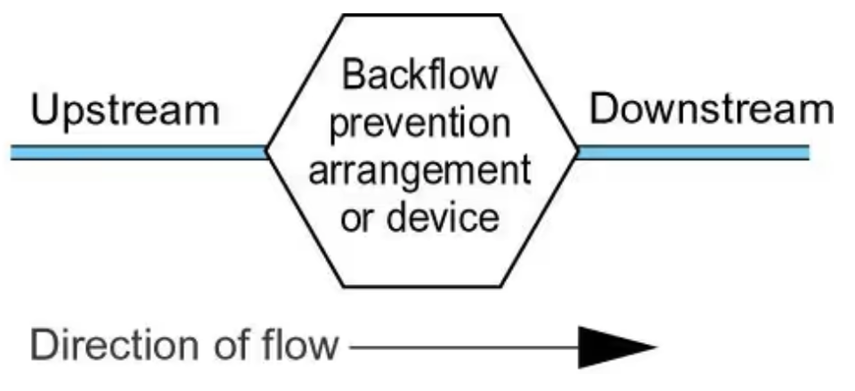
Backflow Protection 


For the purposes of the water fittings regulations in England, Wales and Northern Irelandbyelaws in Scotland, backflow occurs when fluid flows in the opposite to the intended or normal direction of flow. 

There are two types of backflow, back pressure and back siphonage. 

The circumstances which could lead to backflow are a common occurrence across the UK, contamination of public water supplies by backflow of fluids from customers premises is not theoretical. It is an ever present threat to water quality and public health.

Good design and the installation of suitable backflow prevention arrangements are key to avoiding backflow, which is why notification is so important.

Schedule 2 paragraph 15 of the water fittings regulations in England, Wales and Northern Irelandbyelaws in Scotland require every plumbing system to incorporate protection against backflow. This is often referred to as point of use backflow protection. It can be provided by an air or tap gap arrangement or a mechanical backflow prevention device. 

Backflow prevention arrangements and devices permitted under the regulations/byelaws need to be approved by the regulator  or alternatively authorised as a relaxation. Relaxations allow a water undertaker the discretion to accept an arrangement as preventing backflow. 

Wherever practicable plumbing systems should be protected against backflow without the necessity to rely on mechanical backflow protection devices.

Related FAQs

When does schedule 2 paragraph 2 not apply?

<h1 id="when-does-schedule-2-paragraph-2">When does schedule 2 paragraph 2 not apply?</h1><hr><h4 id="when-does-schedule-2-paragraph-2"></h4><p>Providing appropriate and adequate backflow protection against the highest level of risk downstream is installed, an installation not used to supply water for drinking, bathing, food preparation or cooking purposes is exempt from complying with schedule 2 paragraph 2(1). <br></p><p>Please note the backflow protection required needs to be assessed by the local water undertaker and other requirements of the water fittings regulations/byelaws continue to apply.</p><p>&nbsp;</p><p>&nbsp;</p><!--PARTBREAK--><h1 id="topics">FAQs</h1><!--PARTBREAK--><p><br></p>

When can a filling loop be used?

<h1 id="new-pagewhen-can-a-filling-loop">When can a filling loop be used?</h1><hr><p>Where a closed circuit (heating system etc) has been categorised by the water undertaker as a fluid category 3 risk, the installation of a compliant double check valve on the fill point connection to the supply/distribution pipe may be considered as acceptable backflow protection.</p><p>Where a fill point connection incorporates a “flexible connection”, when not in use it is good practice for the hose to be completely disconnected and removed. However, a partial disconnection, that is to say only detaching one end of the hose, may be acceptable providing the disconnection is made between the hose and the backflow prevention device on the supply/distribution pipe.</p><p><strong>Please note:</strong> if the water undertaker has concerns about the likelihood of contamination, or the suitability of a double check valve - for example due either to age, operating temperature or pressure fluctuations – under <a href="https://www.legislation.gov.uk/uksi/1999/1148/schedule/2/paragraph/15/made" target="_blank">schedule 2 paragraph 15(4)</a> they can require the installation of additional backflow protection. Further information about backflow protection can be found in the Guidance section on the Water Reg UK website.</p><p><br></p><!--PARTBREAK--><h1 id="topics">FAQs</h1><!--PARTBREAK--><p><br></p>

What is backflow?

<h1 id="backflow-protection-faqs">What is backflow?</h1><hr><h4 class="p1" id="what-is-backflow"></h4><p class="p1">Backflow occurs when fluid flows in the opposite to the intended or normal direction of flow. There are two types of backflow, back pressure and back siphonage.</p><figure class="img-responsive" style="width: 340px; float: none; margin-left: auto; margin-right: auto; min-width: auto; min-height: auto;"><img src="/images/topics/faqs/flow-normal__pipes__v2.png" class="img-responsive" style="width: 100%"></figure><p>&nbsp;</p><ul><li><p>Backpressure: occurs when the pressure downstream increases above that of the supply pressure, in effect pushing fluids backwards against the intended or normal direction of flow.</p></li></ul><p>&nbsp;<img src="/images/topics/faqs/flow-backpressure__pipes_.png" class="img-responsive" style="display:block;float:none;margin-left:auto;margin-right:auto;width:318px" loading="lazy"></p><ul><li><p>Back siphonage: occurs when the supply pressure drops below that of the system it is supplying creating a depressurisation or vacuum which pulls fluids backwards against the intended or normal direction of flow.</p></li></ul><p>&nbsp;<img src="/images/topics/faqs/flow-back_siphonage__pipes_.png" class="img-responsive" style="width:318px;display:block;float:none;margin-left:auto;margin-right:auto" loading="lazy"></p><p class="p1">The type of backflow risk is dependent upon a number of factors. Good design and the installation of suitable backflow prevention arrangements are key to avoiding backflow, which is why&nbsp;notification&nbsp;is so important.</p><p class="p1">As the circumstances which could lead to backflow are a common occurrence across the UK, contamination of public water supplies by backflow of fluids from customers premises is not theoretical. It is an ever present threat to water quality and public health.</p><p class="p1">As there have been a number of serious contamination events across the UK water undertakers take their role in preventing such incidents very seriously. Where infringements are suspected or identified they will act, not only to protect water quality and public health, but also to support owners and occupiers of premises to meet their legal obligations.</p><p class="p1">Where contamination incidents occur, it is likely that enforcement action, including criminal proceedings, will be taken against those who fail to meet their legal obligations.</p><p>&nbsp;</p><!--PARTBREAK--><h1 id="topics">FAQs</h1><!--PARTBREAK--><p><br></p>

What is contamination?

<h1 id="backflow-protection-faqs">What is contamination?</h1><hr><h4 class="p1" id="what-is-contamination"></h4><p class="p1">Water undertakers are legally required to ensure the drinking water they supply is wholesome. Contamination occurs when there is a change in water quality irrespective of whether or not it is harmful to health</p><p>&nbsp;</p><p>&nbsp;</p><p>&nbsp;</p><!--PARTBREAK--><h1 id="topics">FAQs</h1><!--PARTBREAK--><p><br></p>

Who assess backflow risks?

<h1 id="who-assess-backflow-risks">Who assess backflow risks?</h1><hr><h4 id="who-assess-backflow-risks"></h4><p>As part of their statutory duty to enforce the water fittings regulations in <a href="https://www.legislation.gov.uk/uksi/1999/1148/contents/made">England, Wales</a> and <a href="https://www.legislation.gov.uk/nisr/2009/255/contents/made">Northern Ireland</a>, <a href="https://www.scottishwater.co.uk/-/media/ScottishWater/Document-Hub/Business-and-Developers/Byelaws-and-Trade-Effluent/170718swbyelawsexplained.pdf">byelaws in Scotland</a>, the local water undertaker will identify the level of backflow protection needed. This categorisation will be based on a number of factors including the highest downstream fluid category risk the fitting is or is likely to be subject.</p><p>&nbsp;</p><!--PARTBREAK--><h1 id="topics">FAQs</h1><!--PARTBREAK--><p><br></p>

What is a backflow prevention arrangement or device?

<h1 id="what-is-a-backflow-prevention-arrangement">What is a backflow prevention arrangement or device?</h1><hr><h4 class="p1" id="a-backflow-prevention-arrangement-or-device"></h4><p class="p1">It is in effect a barrier intended to prevent contaminated fluid flowing backwards.</p><figure class="img-responsive" style="float: left; width: 450px; margin-right: 10px; margin-left: 10px; min-width: auto; min-height: auto;"><img src="/images/topics/backflow_protection.png" style="width: 100%"></figure><p class="p1"><br></p><p><br></p><p><br></p><p><br></p><p><br></p><p class="p1"><br></p><p class="p1"><a href="https://www.legislation.gov.uk/uksi/1999/1148/schedule/2/paragraph/15">Schedule 2 paragraph 15</a>&nbsp;of the water fittings regulations in&nbsp;<a href="https://www.legislation.gov.uk/uksi/1999/1148/contents/made">England, Wales</a>&nbsp;and&nbsp;<a href="https://www.legislation.gov.uk/nisr/2009/255/contents/made">Northern Ireland</a>,&nbsp;<a href="https://www.scottishwater.co.uk/-/media/ScottishWater/Document-Hub/Business-and-Developers/Byelaws-and-Trade-Effluent/170718swbyelawsexplained.pdf">byelaws in Scotland</a>&nbsp;require every plumbing system to incorporate protection against backflow. This is often referred to as point of use backflow protection. It can be provided by an&nbsp;air or tap gap arrangement or a mechanical backflow prevention device.&nbsp;</p><p class="p1">Backflow prevention arrangements and devices permitted under the regulations/byelaws need to be approved by the&nbsp;regulator&nbsp; or alternatively authorised as a relaxation. Relaxations allow a water undertaker the discretion to accept an arrangement as preventing backflow.&nbsp;</p><p class="p1">The regulator rates a backflow protection arrangement or device for suitability against contamination risk (fluid categories) and types of backflow risk - back siphonage or back pressure. They should always be accessible for inspection, maintenance and replacement.</p><figure class="img-responsive" style="float: left; margin-right: 20px; margin-bottom: 20px; width: 181px; min-width: auto; min-height: auto;"><img src="/images/topics/faqs/7-6-cr_dcv__1_.png" class="img-responsive" style="width: 100%"></figure><p>Backflow prevention devices, are required to be corrosion resistant. For example, for metallic backflow prevention devices manufactured of gunmetal or other dezincification resistant materials. Dezincification water fittings are typically marked with a CR symbol.</p><p>Wherever practicable plumbing systems should be protected against backflow without the necessity to rely on mechanical backflow protection devices.</p><p>&nbsp;</p><p>&nbsp;</p><!--PARTBREAK--><h1 id="topics">FAQs</h1><!--PARTBREAK--><p><br></p>

Type AA air gaps

<h1 id="type-aa-air-gaps">Type AA air gaps</h1><hr><p>A Type AA air gap is a non-mechanical backflow prevention arrangement comprising of an inlet which discharges water into a cistern, vessel, fitting or appliance (receiving vessel) and an outlet. Depending on the outcome of an assessment by the local water undertaker it can feed a single or multiple installations.</p><p style="text-align: start;">A Type AA air gap is rated by the Regulators as suitable backflow protection against both back siphonage and back pressure at the highest level of contamination risk,&nbsp;fluid category&nbsp;5.</p><figure class="img-responsive" style="float: none; margin-left: auto; margin-right: auto; width: 400px; min-width: auto; min-height: auto;"><img src="/images/topics/backflow/15-type-aa_with_ss_.png" style="width: 100%"></figure><p><br></p><p>A summary of some of the key requirements for a Type AA air gap is given below:</p><ol><li><p>The supply pipe and inlet control must be external to the receiving vessel and fixed so the air gap is maintained and unrestricted.</p></li><li><p>The air gap is an unobstructed and complete physical break between the lowest point of discharge and the spillover level of the contents of the receiving vessel. Measured vertically it must be no less than 20 mm or twice the internal diameter of the supply whichever is the greater.</p></li><li><p>The spillover level is the level at which the contents of receiving vessel spill over the top edge when the inflow of water exceeds the outflow through the outlet i.e. demand.</p></li><li><p>The spillover is unrestricted.</p></li><li><p>If the supply pipe feeding the inlet or the inlet itself comes into contact with the contents of the receiving vessel, for example due to splashing or foaming, then the air gap is considered to be compromised and must be increased to the point no contact occurs.</p></li><li><p>Type AA air gaps should be inspected, and as necessary, maintained every 6 months (BS EN 806: 5)</p></li></ol><p><br></p><p><br></p><!--PARTBREAK--><h1 id="faqs">FAQs</h1><!--PARTBREAK--><p><br></p>

Type AB air gaps

<h1 id="type-ab-air-gaps">Type AB air gaps</h1><hr><p>A Type AB air gap is a non-mechanical backflow prevention arrangement comprising of an inlet which discharges water into a cistern, vessel, fitting or appliance (receiving vessel) fitted with an outlet and a rectangular weir or ‘slot’ overflow. Depending on the outcome of an assessment by the local water undertaker it can feed a single or multiple installations.</p><p style="text-align: start;">A Type AB air gap is rated by the Regulators as suitable backflow protection against both back siphonage and back pressure at the highest level of contamination risk,&nbsp;fluid category&nbsp;5.</p><figure class="img-responsive" style="min-width: auto; min-height: auto; float: none; margin-left: auto; margin-right: auto; width: 400px;"><img src="/images/topics/backflow/15-type-ab_with_ss_.png" style="width: 100%"></figure><p>A summary of some of the key requirements applicable to a Type AB air gap is given below:</p><ol><li><p>The air gap is an unobstructed and complete physical break between the lowest point of discharge and the critical water level of the weir overflow. Measured vertically it must be no less than 20 mm or twice the internal diameter of the supply whichever is the greater.</p></li><li><p>The critical level (sometimes referred to as h) is the fluid level in the receiving vessel under fault conditions i.e. when the outlet is closed but the inlet continues to discharge. It is measured at least 2 seconds after closing the water inlet</p></li><li><p>Whether sited internally or externally (as shown in the diagram opposite) the weir overflow must be rectangular (non-circular) and capable of accommodating discharge under fault conditions. Where a screened mesh is installed consideration should be given to the impact this may have on discharge flow. The air gap can be confirmed by test or calculation using the Type AB air gap&nbsp;<a href="https://www.waterregsuk.co.uk/information/tools">calculator.</a></p></li><li><p>Neither the fluid pathway to the overflow nor the discharge from it should be&nbsp;<a href="https://www.waterregsuk.co.uk/guidance/backflow-protection/backflow-protection/backflow-protection1/what-is-an-unrestric/">restricted</a>. For example, there should be a sufficient gap between the overflow and any surface to accommodate full discharge unimpeded during fault conditions.</p></li><li><p>Submerged supply pipes are not permitted. If the supply pipe feeding the inlet or the inlet itself comes into contact with the contents of the receiving vessel, for example due to splashing or foaming, then the air gap is considered to be compromised and must be increased to the point no contact occurs.</p></li><li><p>Type AB air gap installations, including screened mesh, should be inspected, cleaned and as necessary maintained every 6 months (BS EN 806: 5)</p></li></ol><p><br></p><viewer-3d style="box-sizing: border-box; font-family: -apple-system, system-ui, BlinkMacSystemFont, &quot;Segoe UI&quot;, Roboto, &quot;Helvetica Neue&quot;, Arial, sans-serif;"><div class="block svelte-1wjbz9j"><div class="container svelte-1uqz219"></div></div></viewer-3d><div><div class="duoEditArea"><p><br></p></div></div><p><br></p><p><br></p><p><br></p><p><br></p><!--PARTBREAK--><h1 id="faqs">FAQs</h1><!--PARTBREAK--><p><br></p>

Type AC air gaps

<h1 id="type-ac-air-gaps">Type AC air gaps</h1><hr><p>A Type AC air gap is a non-mechanical backflow prevention arrangement comprising of a vented, but submerged inlet that discharges into a cistern, vessel, fitting or appliance fitted (receiving vessel) with an outlet and circular overflow.</p><p style="text-align: start;">A Type AC air gap is rated by the Regulators as suitable backflow protection against both back siphonage and back pressure for contamination risks no greater than&nbsp;fluid category&nbsp;3 .</p><figure class="img-responsive" style="float: none; margin-left: auto; margin-right: auto; width: 400px; min-width: auto; min-height: auto;"><img src="/images/topics/backflow/15-type-ac_with_ss_.png" style="width: 100%"></figure><p>A summary of some of the key requirements applicable to a Type AC air gap is given below:</p><ol><li><p>The air gap is an unobstructed and complete physical break between the lowest point of the vent (air inlet) and the critical water level of the weir overflow. It must be no less than 20 mm or twice the internal diameter of the supply whichever is the greater.</p></li><li><p>The critical level is the fluid level in the receiving vessel under fault conditions i.e. when the outlet is closed but the inlet continues to discharge. It is measured at least 2 seconds after closing the water inlet.</p></li><li><p>Supply pipes maybe submerged but adjustable or dismantlable joints on the are not permitted below the critical water level.</p></li><li><p>The overflow shall be not less than 19mm (internal diameter).</p></li><li><p>Where they discharge to drain the overflow and warning pipe must be fitted with an air break to drain or equivalent prior to the drain connection.</p></li><li><p>Type AC air gap installations should be inspected, and as necessary maintained every 12 months (BS EN 806: 5)</p></li></ol><p style="text-align: start;" class="MsoNormal"><br></p><p><br></p><p><br></p><!--PARTBREAK--><h1 id="faqs">FAQs</h1><!--PARTBREAK--><p><br></p>

Type AD air gap

<h1 id="type-ad-air-gaps">Type AD air gaps</h1><hr><p>A Type AD air gap, sometime call a ‘jump jet’ is a non-mechanical backflow prevention arrangement comprising of a horizontal injector which ‘jets’ water into a cistern, vessel, fitting or appliance fitted (receiving vessel) and an air break to drain open to atmosphere.</p><p style="text-align: start;">A Type AD is rated by the Regulators as suitable backflow protection against both back siphonage and back pressure at the highest level of contamination risk,&nbsp;fluid category&nbsp;5.</p><figure class="img-responsive" style="float: none; margin-left: auto; margin-right: auto; width: 400px; min-width: auto; min-height: auto;"><img src="/images/topics/backflow/15-type-ad_with_ss_.png" style="width: 100%"></figure><p><br></p><p>A summary of some of the key requirements applicable to a Type AD air gap is given below:</p><ol><li><p>The air gap is an unobstructed and complete physical break between the terminal point of the injector and inlet orifice of the receiving vessel. Measured horizontally it must be no less than 20 mm or twice the internal diameter of the supply whichever is the greater.</p></li><li><p>The air break to drain must be open to atmosphere and capable of draining the maximum flow rate without submerging or coming into contact with the inlet.</p></li><li><p>The inlet must not come into contact with any splashing, drips or run off from the receiving vessel.</p></li><li><p>Type AD air gap installations should be inspected, and as necessary maintained every 6 months (BS EN 806: 5)</p></li></ol><p style="text-align: start;" class="MsoNormal"><br></p><p><br></p><!--PARTBREAK--><h1 id="faqs">FAQs</h1><!--PARTBREAK--><p><br></p>


Back to all Topics


We use cookies to give you the best possible experience with Water Regs UK. Some are essential to provide website functions and ensure the website is secure. We also use cookies to help us understand how people use the site and to make improvements. Click "Accept All" to enable recommended settings or click "Manage cookies" to adjust your settings. For more details, see our Cookie Policy.