
The water fittings regulations in England, Wales and Northern Ireland, byelaws in Scotland are legal requirements which apply to all premises which have, or will have, a mains water supply, even it is only a backup supply.
An important item of public health legislation, their purpose is to protect drinking water supplies. Their objective is to prevent contamination, misuse, waste, undue consumption or erroneous measurement of water. They do this by setting legal requirements for the design, installation, operation and maintenance of water fittings, including water-using appliances.
Any premises with, or which will have, a mains water supply falls under the scope of the water fittings regulations in England, Wales and Northern Ireland, byelaws in Scotland.
These regulations/byelaws place a legal duty on the owners or occupiers of premises and anyone undertaking plumbing work for them to ensure all the applicable requirements are complied with. Failure to do so is a criminal offence.
The water fittings regulations/byelaws apply to all premises with a mains water supply, even if it is only a backup supply arrangement.
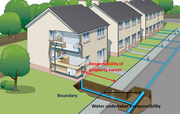
The regulations/byelaws apply to all water fittings (both above and below ground) and water using appliances from the point where the mains water enters the property (usually the stop tap at the property boundary) to the point it is used by the consumer.
The current regulations/byelaws do not apply to plumbing systems which were lawfully installed
under previous water fittings byelaws. However, water undertakers can require changes to be made to such systems under other legislation.
 We all take it for granted when we turn the tap on there will be water and it will be safe to drink.
The water fittings regulations/byelaws exist to help ensure this is the case. Their purpose is to prevent customers plumbing systems contaminating and wasting drinking water supplies, an important public health measure to protect both those within the premises and the wider community.
The need for everyone to have access to clean, safe drinking water is why it is so important for those responsible for water fittings to ensure plumbing systems are compliant with all, not just some of the applicable parts of the regulations/byelaws.
Additional information
Those responsible for water fittings should ensure plumbing systems are compliant with all, not just some of the applicable parts of the regulations/byelaws.
Water fittings themselves have to be compliant
Where, and the way in which water fittings are installed has to be compliant
How plumbing systems are used and maintained has to be compliant
Risk | Examples of measures which could be taken |
Water fittings, including water using appliances, contaminate or waste drinking water supplies | Ensure water fittings are of an appropriate quality and standard as well as suitable for installation |
Proposed changes to plumbing systems contaminate or waste drinking water supplies | Notification this is a simple and essential check which will highlight potential contamination or waste concerns Consider using an approved contractor |
Existing plumbing system installations: changes to, or the way they are operated contaminates or wastes drinking water supplies | Be aware of the legal obligations imposed by the water fittings regulations/byelaws, including the need to notify Ensure plumbing is installed and maintained in accordance with the manufacturer’s installation instructions and any relevant regulatory requirements. Use the installation guidance published by the local water undertaker and Water Regs UK Consider using an approved contractor In the case of specific installation queries contact the local water undertaker for advice |
The current regulations/byelaws do not apply to plumbing systems which were lawfully installed under previous water fittings byelaws. However, water undertakers can require changes to be made to such systems under other items of legislation.
Additional information
Water undertakers have a legal duty to enforce the water fittings regulations in England, Wales and Northern Ireland, byelaws in Scotland, in their area of supply.
To check the requirements are being complied with water undertakers will carry out inspections and take enforcement action when contraventions/offences are identified.
For further details please refer to water undertakers’ enforcement policies.
A water company which has the statutory duty to supply water and/or sewerage services to premises within a specific geographical area.
Additional information

If a premises has any form of mains water supply, then in many cases the water fittings regulations in England, Wales and Northern Ireland, byelaws in Scotland, make it a legal requirement (regulation 5) for the local water undertaker to be given advanced notice of any proposed plumbing work. This is an important simple and essential check to minimise the risk to water supplies.
The water undertaker has 10 working days to respond to a valid notification. The proposed work should not start until after the 10 days is up.
The water undertaker can either decline or grant consent. If consent is granted conditionally then these conditions must be met.
If no response is received consent is deemed to have been granted. The proposed plumbing work can proceed but the owner/occupier has the legal obligation to ensure it is fully compliant with the water fittings regulations/byelaws.
The conditions of consent will be found in the consent letter issued by the local water undertaker. This will have been sent to the address listed in the advanced notification.
If there are any questions relating to the approval granted, please contact the local water undertaker for further information
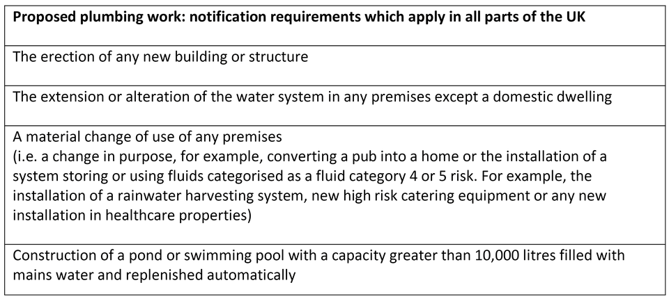
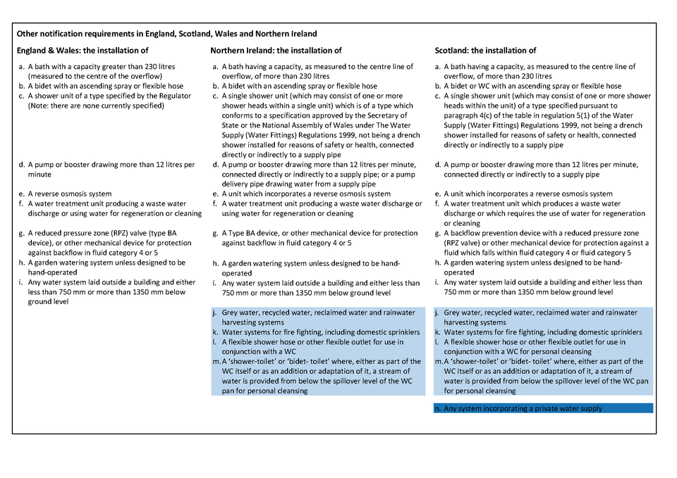
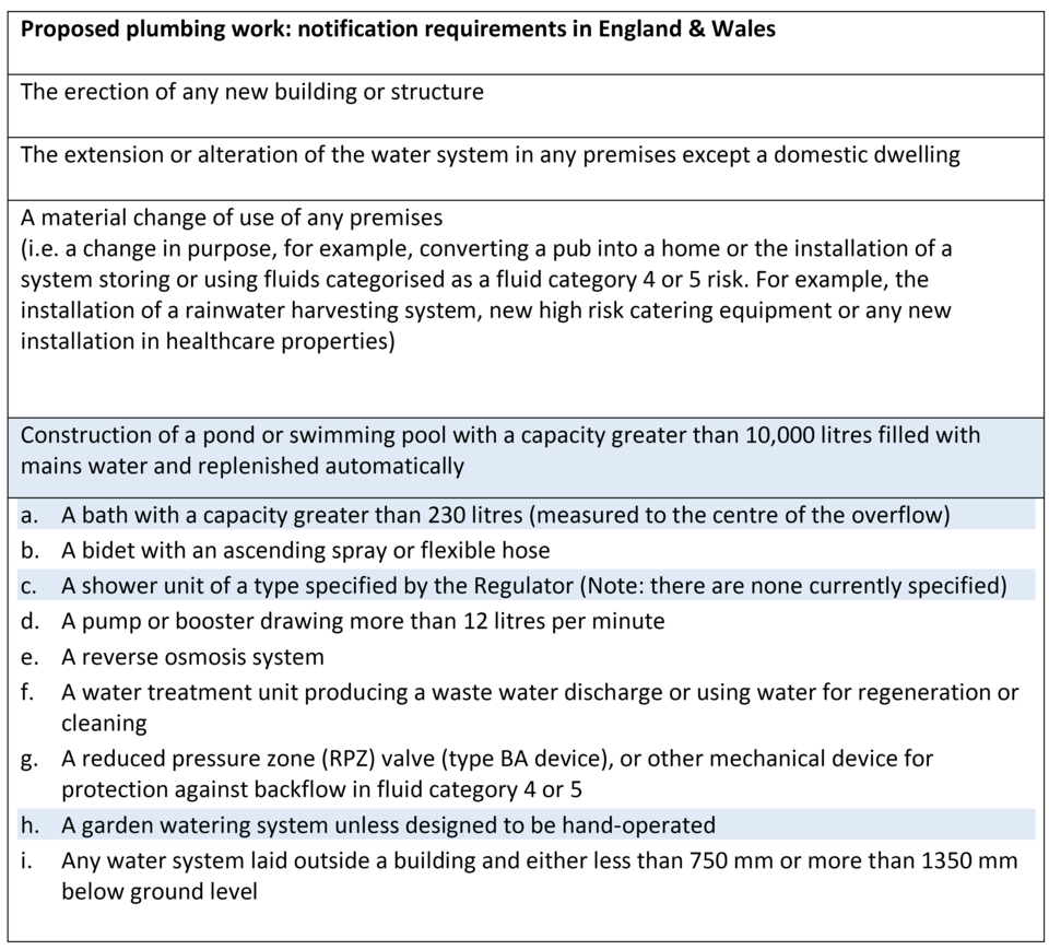
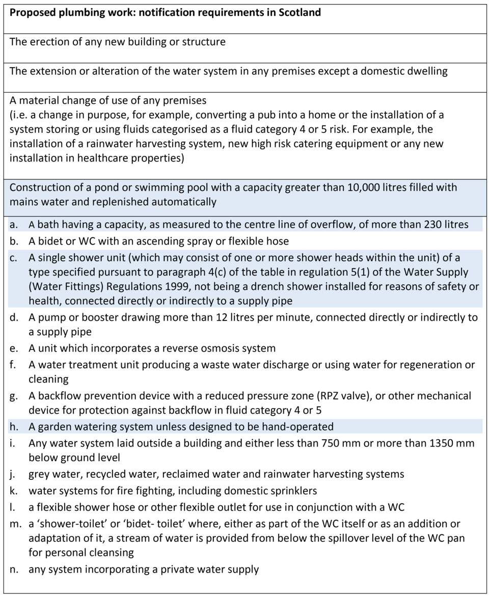
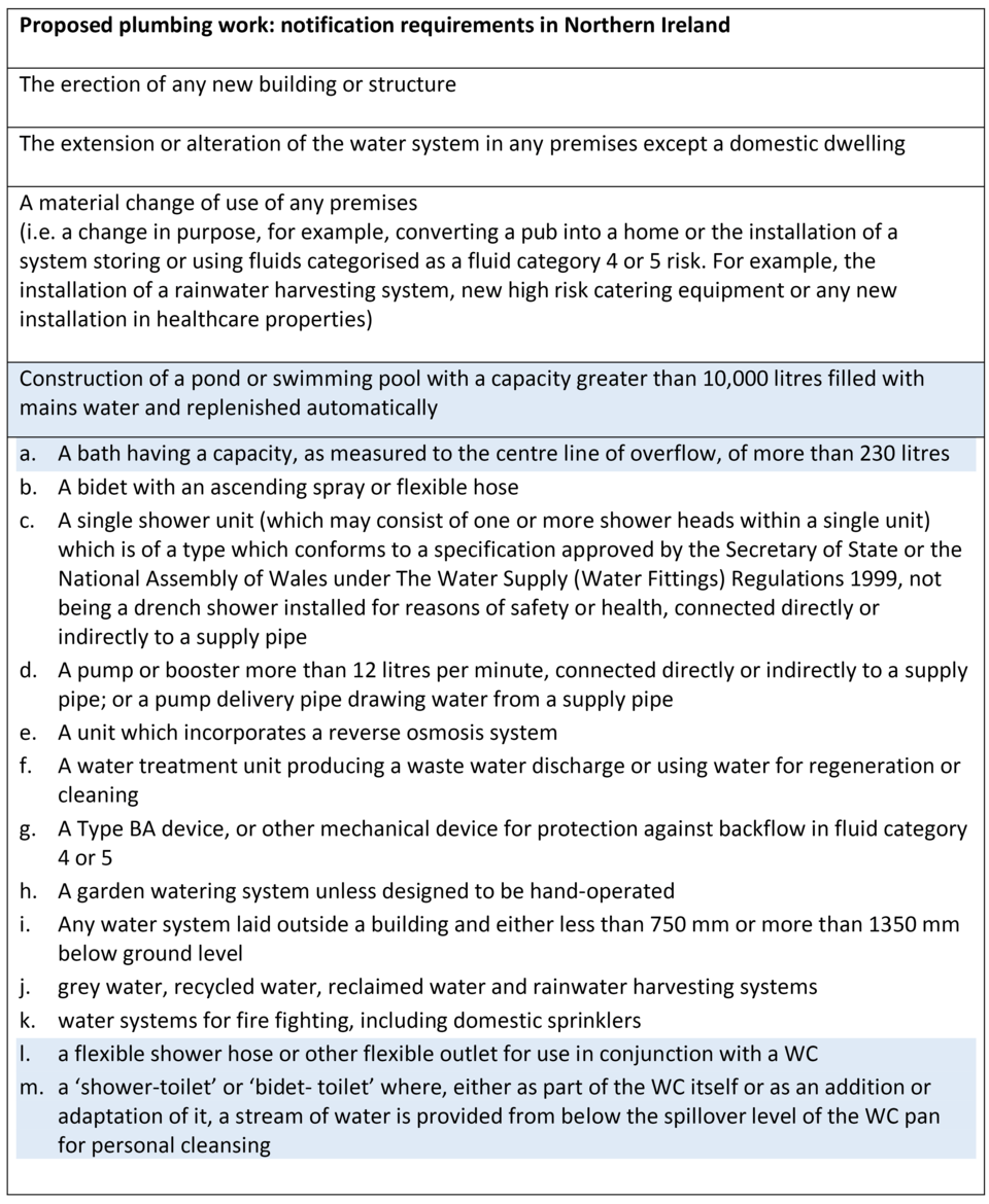
Although broadly similar there are differences in the notification requirements in England, Scotland, Wales and Northern Ireland. Any questions please contact the local water undertaker for advice.
Notification requirements which are the same in England, Wales, Scotland and Northern Ireland.
Many water undertakers have their own notification forms and dedicated contact information which can be found on the water undertaker’s website and here. It is important to use the local water undertakers form especially when submitting electronically.
If the local water undertaker does not provide a form, for a notification to be valid it must include as a minimum:
The name and address of the person giving notice and, if different, the name and address of the person to whom the consent should be sent.
A description of the proposed work or material change of use.
The location of the premises and their use or intended use.
If using an approved contractor their name
Except for the items highlighted below a plan of those parts of the premises which relate to the proposed work and a diagram showing the pipework and fittings to be installed.
Scottish Water has its own notification form and dedicated contact as well as other information which can be found here .
Any questions please contact Scottish Water for advice.
Please note except for the items highlighted below a plan of those parts of the premises which relate to the proposed work and a diagram showing the pipework and fittings to be installed will be required.
Northern Ireland Water has its own notification form and dedicated contact as well as other information which can be found here .
Any questions please contact Northern Ireland Water for advice.
Please note except for the items highlighted below a plan of those parts of the premises which relate to the proposed work and a diagram showing the pipework and fittings to be installed will be required.
A material change of use is defined in the water fittings regulations in England, Wales and Northern Ireland, byelaws in Scotland
It is a change in the purpose for which a premises is used or the circumstances in which water within that premises will be used, specifically the introduction of new systems or appliances which are categorised as posing a fluid category 4 or 5 risk.
For example:
The conversation of a house into a business premises or private business to a public building.
A change of business use
The installation of a new rainwater harvesting system, new high risk catering equipment or any new installation in healthcare.
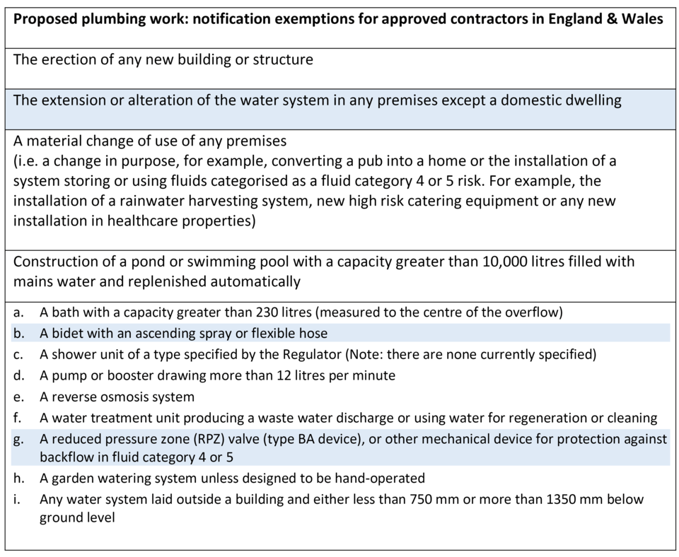
For the purpose of the water fittings regulations in England, Wales and Northern Ireland, byelaws in Scotland an approved contractor is a member of one of the following schemes.
Chartered Institute of Plumbing and Heating Engineering (CIPHE)
Scottish and Northern Ireland Plumbing Employers’ Federation (SNIPEF)
Providing:
Their scheme is recognised by the local water undertaker
The proposed work is not a material change of use
The scope of their membership covers the type of plumbing work undertaken
They comply with their scheme terms and conditions
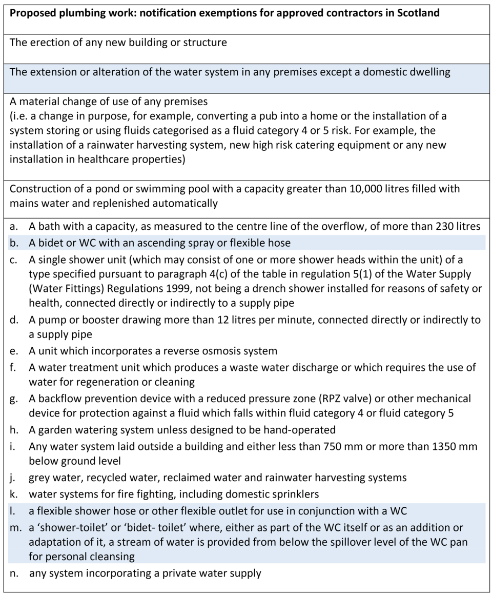
An approved contractor installing the items highlighted in the list below, may not have to provide advanced notification before starting work. However, on completion they will be required to send a certificate of compliance for the work to the local water undertaker as well as issuing one to their client.
Please note: notification exemptions for those approved contractors who are members of sector schemes is typically restricted to the alteration or extension of plumbing systems. For further information contact the scheme
Please note: due to both differences in notification requirements across the UK and variation in individual approved contractor schemes terms and conditions it is important to check whether advanced notification is required.
For the purpose of the water fittings regulations in England, Wales and Northern Ireland, byelaws in Scotland an approved contractor is a member of one of the following schemes.
Chartered Institute of Plumbing and Heating Engineering (CIPHE)
Scottish and Northern Ireland Plumbing Employers’ Federation (SNIPEF)
Providing:
Their scheme is recognised by Scottish Water
The proposed work is not a material change of use
The scope of their membership covers the type of plumbing work undertaken
They comply with their scheme terms and conditions
An approved contractor installing the items highlighted in the list below, may not have to provide Scottish Water with advanced notification before starting work. However, on completion they will be required to send a certificate of compliance for the work to Scottish Water as well as issuing one to their client.
Any questions please contact the Scottish Water for advice.
Please note: notification exemptions for those approved contractors who are members of sector schemes is typically restricted to the alteration or extension of plumbing systems. For further information contact the scheme
Please note: due to both differences in notification requirements across the UK and variation in individual approved contractor schemes terms and conditions it is important to check whether advanced notification is required.
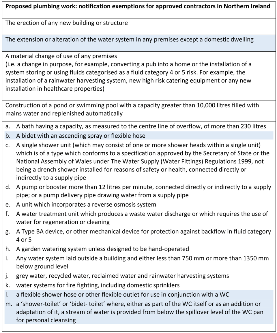
For the purpose of the water fittings regulations in England, Wales and Northern Ireland, byelaws in Scotland an approved contractor is a member of one of the following schemes.
Chartered Institute of Plumbing and Heating Engineering (CIPHE)
Scottish and Northern Ireland Plumbing Employers’ Federation (SNIPEF)
Providing:
Their scheme is recognised by Northern Ireland Water
The proposed work is not a material change of use
The scope of their membership covers the type of plumbing work undertaken
They comply with their scheme terms and conditions
An approved contractor installing the items highlighted in the list below, may not have to provide Northern Ireland Water with advanced notification before starting work. However, on completion they will be required to send a certificate of compliance for the work to Northern Ireland Water as well as issuing one to their client.
Any questions please contact the Northern Ireland Water for advice.
Please note: notification exemptions for those approved contractors who are members of sector schemes is typically restricted to the alteration or extension of plumbing systems. For further information contact the scheme
Please note: due to both differences in notification requirements across the UK and variation in individual approved contractor schemes terms and conditions it is important to check whether advanced notification is required.
The requirement to notify the proposed installation of 'a pump or booster drawing more than 12 litres per minute, connected directly or indirectly to a supply pipe' applies to all pumps capable of delivering any flow rate greater than 12 litres per minute.
For example, a shower which is supplied with water through a pump (located either upstream or downstream of the mixing valve) capable of delivering more than 12 litres/minute.

Pipework should be laid at a depth of not less than 750 mm (to limit the effect of freezing and mechanical damage) and no greater than 1350 mm deep. They should be embedded in non-abrasive materials. Where this cannot be achieved in all circumstances the consent of the local water undertakers must be obtained via notification.
Where the local water undertaker consents to pipework being laid at less than 750 mm it should be installed as deep as possible below ground level and protected against warming, freezing and mechanical damage (for example due to ground movement).
Pipework should not be installed above ground level is not permitted without the agreement of the local water undertaker.
To help prevent contamination and waste of mains water supplies the water fittings regulations in England, Wales and Northern Ireland, byelaws in Scotland include specific requirements for water fittings. These include the legal requirement to be of an appropriate quality and standard for installation [regulation 4 (1)(a) & 4(2)].
This regulation requires water fittings, and water using appliances, to either:
Conform to an appropriate British Standard (or some other national specification which provides an equivalent level of protection and performance)
Or
Conform to a specification approved by the regulators
If the water conveyed by these fittings needs to be wholesome – drinking water standard - any non-metallic materials or components within the fitting or appliance which comes into contact with water must also conform to the current version of BS 6920 (or an equivalent).
Any questions please contact the local water undertaker for advice.
This is evidence to show a water fitting is of an appropriate quality and standard for installation.
Water undertakers will consider evidence of compliance provided on a case and site specific basis.
Whilst this evidence must satisfy another regulation [4(2)], water undertakers have no preference for, or require it to be in a specific form. Typically, they will consider declarations of performance issued against designated standards, product certification and test reports.
Please note:
Because a water fitting must comply with all parts of the regulations being of an appropriate quality and standard does not, of itself, guarantee compliance with the regulations.
The latest available edition or version of guidance or specifications should always be used.
In respect of equivalence water undertaker retain absolute discretion in assessing whether a national specification provides an equivalent level of protection and performance to that specified in an appropriate British Standard. For information regarding the equivalence of a performance specification please contact your water undertaker.
For further information please refer to Regulation 4(1)(a) compliance guidance and BS 6920 Compliance Overview.
Any questions please contact the local water undertaker for advice.
Some but not all appliances incorporate backflow protection which satisfies UK requirements, conformity with BS EN 61770 does not. If the backflow protection built in is not adequate the appliance must be supplied via an independent appropriate form of backflow protection.
Please refer to the 'Whitegoods' information leaflet for further information.
Establishing whether a water fitting is suitable for installation is dependent upon a number of factors including but not limited to:
Water fittings must be of an appropriate quality and standard
System design, things considered include but are not limited to compatibility:
with other water fittings within a plumbing system (e.g the potential for galvanic action)
system operational parameters (e.g. the maximum* and minimum pressure, temperature and flow the systems will be operating at)
Location specific factors, things considered include but are not limited to:
the environment (e.g. ground or airborne contamination, the risk of frost damage, corrosion or dezincification)
product installation requirements and/or constraints (e.g. installed where light is excluded or only above ground)
installation backflow risks (e.g. the need for backflow protection to be installed)
Requirements of schedule 2 as applicable.
If the proposed plumbing work is notifiable, the suitability of water fittings will be assessed as part of the notification process.
If the installation is not notifiable there remains a legal obligation for the installer and premises owner or occupier to ensure the plumbing work is fully compliant with the water fittings regulations in England, Wales and Northern Ireland, byelaws in Scotland. Therefore, if in doubt, contact the local water undertaker for advice.
*Please note all water fittings must be capable of withstanding an internal water pressure of not less than 1½ times the maximum pressure it will be subject to in operation.
Providing appropriate and adequate backflow protection against the highest level of risk downstream is installed, an installation not used to supply water for drinking, bathing, food preparation or cooking purposes is exempt from complying with schedule 2 paragraph 2(1).
Please note the backflow protection required needs to be assessed by the local water undertaker and other requirements of the water fittings regulations/byelaws continue to apply.
When designing a compliant plumbing system a number of factors need to be considered, including but not limited to:
Avoiding the risk of contamination or damage resulting from the environment in which the system is to be installed or due to the design itself.
The required and attainable supply pressure and other operational parameters
User expectations and whether these are achievable
Suitability of water fittings for use
Providing appropriate, adequate backflow protection.
Water efficiency
Limiting waste.
Useful sources of information include BS EN 806 and BS 8558
To help prevent waste and contamination all pipe and fittings systems must be of an appropriate quality and standard and suitable for the circumstances in which they will be used.
Before installing a pipe and fittings system key considerations will include but are not limited to:
The compatibility of the pipe and fittings. For example, to ensure connections are watertight and configured to prevent galvanic action.
Whether the pipework is to be installed above or below ground
Where the pipework is to be installed. For example, in contaminated ground, in a duct and potentially exposed to construction materials and/or water vapour, somewhere exposed to sunlight or sources of heat.
What water temperatures and pressures the pipework will be exposed to. For example, hot or cold water only, heating systems, maximum operating pressure and thermal shock.
In the case of metallic water fittings, the possibility of corrosion due to galvanic action and dezincification.
Useful sources of information include BS EN 806 and BS 8558
Please note:
All water fittings should be resistant to corrosion. In the case of mechanical backflow prevention devices and metallic fittings which are not going to be readily accessible, in addition to being corrosion resistant these should be manufactured from materials which are not susceptible to dezincification. For example, gunmetal or CR brass.
As non-metallic pipe and fittings can be affected by sunlight and/or allow ingress of light, which is known to promote the growth of algae, consideration should be given to whether protective measures to exclude light are necessary.
Adhesive joints are not acceptable below ground.
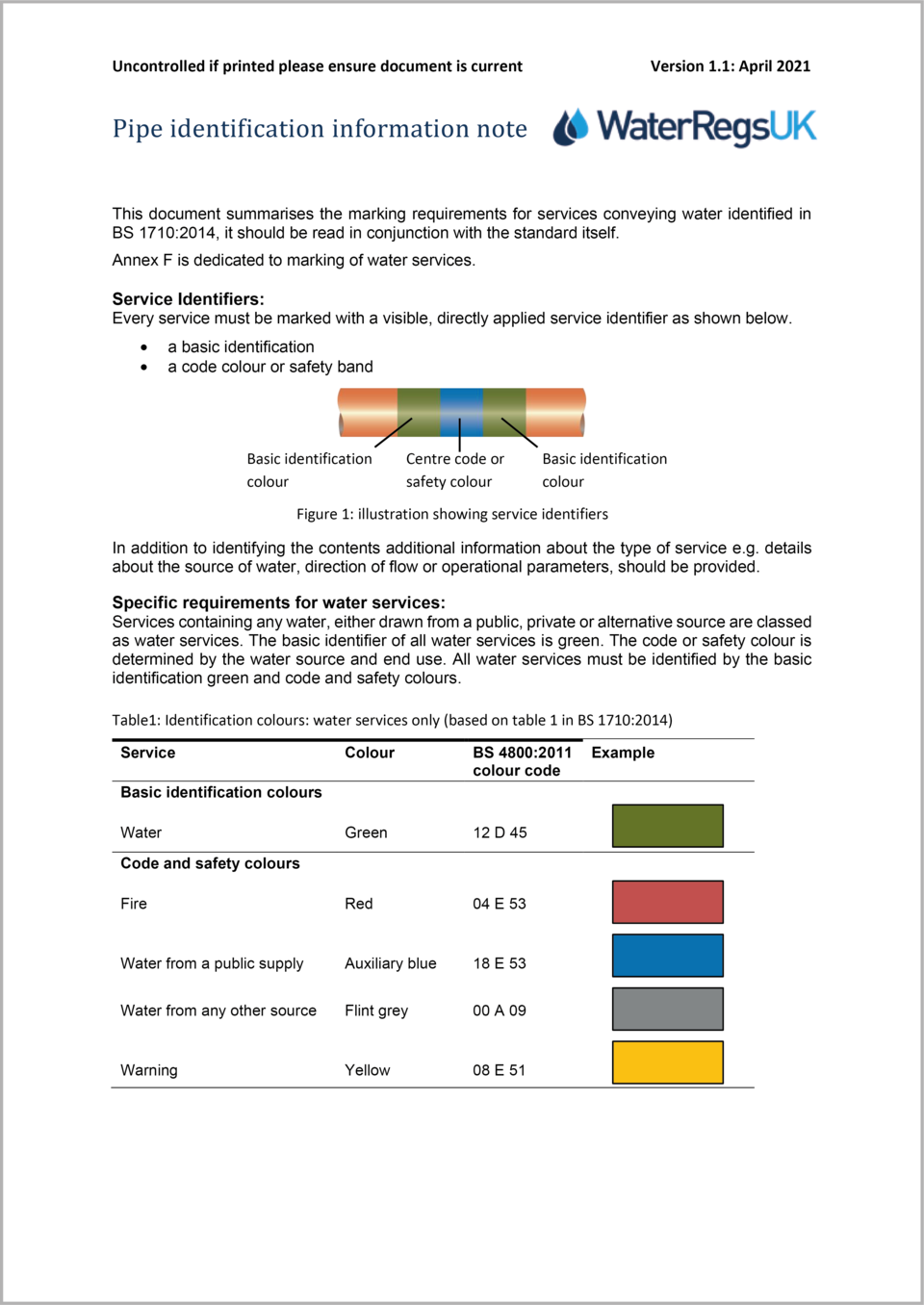
Irrespective of what fluid is being conveyed all pipework, whether installed above or below ground, should be marked in accordance with the latest version of BS 1710.
To identify what parts of a plumbing system they control, servicing valves should be labelled.
For further information please refer to the pipe identification information leaflet
One way is to measure the supply pressure at a tap directly supplied from the mains at a time when there is little demand, such as at night.
Please note:
This will not take into consideration any transient or surge pressures which may be generated within the system. For example water hammer resulting from the rapid closure of a valve within the system.
Water fittings must be able of accommodating 1½ times the maximum operating pressure.
To minimise the risk of contamination resulting from microbial growth and wastage due to taps left to run, cold water storage and distribution systems should be designed and installed to maintain a temperature not exceeding 20oC.
Plumbing systems should be designed and installed to ensure there is regular flow through.
To prevent undue warming, it is good practice to insulate both hot and cold water pipework. Unless it is adequately protected water fittings should not be installed where it could be exposed to heat sources, such as other services or sunlight.
For further information please refer to BS EN 806, BS 8558 and HSE Legionella ACOP.
Joints on concealed pipework are likely to lose their integrity over time and therefore should only be considered where unavoidable.
To prevent waste there needs to be provision to access any joints or water fittings which require maintenance, such as backflow prevention devices, valves which control the flow and any other operational fitting.
To minimise waste when maintaining or replacing water fittings (including water using appliances) servicing valves should be installed as close as practicable to any part of a plumbing system performing a specific task.
Similarly to minimise waste when draining down systems not in use servicing valves and drain taps should be installed as close as practicable to any part of a plumbing system performing a specific task.
Servicing valves should be labelled to indicate what parts of a plumbing system they control.
In the case of inlet valves supplying toilet or urinal flushing cisterns and cold water storage, consideration should be given to pressure surges resulting from operation of the servicing valve.
Please note: drain taps should not be buried or covered with soil, or installed so that they are submerged, or likely to be submerged.
Stop valves isolate the supply to premises.
To help minimise waste stop valves should be labelled to indicate what parts of a plumbing system they control.
Stop valves should be installed on the supply pipe in a readily accessible location either inside or immediately outside the premises.
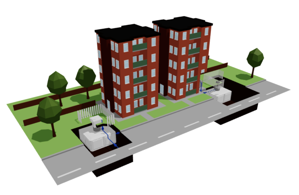
In the case of properties with multiple occupants, such as a block of flats, in addition to the customers own stop tap, a stop valve for maintenance or communal use should be installed.
When selecting a stop valve for use by owner/occupiers consideration should be given to ease and speed of operation, including the effect of sudden changes in supply pressure.
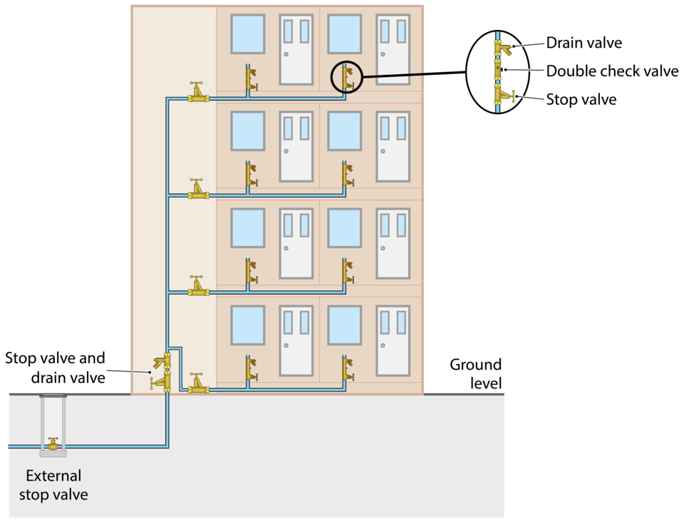
Please note: the illustrations above are examples of acceptable locations for stop valves. Whilst not shown other requirements apply, including but not limited to the installation of drain taps, servicing valves and backflow protection.
For further information contact the local water undertaker.
Owners/occupiers should always ensure the local water undertaker is aware if a premises has both a mains drinking water and alternative water supply, such as a borehole or rainwater.
No. Alternative water supplies should never be directly connected to the mains drinking water.
Where mains water and other water sources, such as rainwater, recycled water, river water and borehole supplies, combine it is essential to notify the relevant water undertaker to ensure adequate backflow protection arrangements are installed.
The only legal and safe way to combine mains and another source of water is to use an arrangement called a break tank which enables separation of supplies. Typically, this is done using a Type AA or Type AB air gap the key features being:
An unrestricted or weir spill over
The pipework supplying the mains water must be external to the tank
The mains water feed must discharge at a higher level than and maintain a minimum clearance (twice the internal diameter (2D) of the supply pipework or 20 mm whichever is the greater) from those another sources
The water in the tank should not come into contact with the mains water inlet for example as a result of splashing.
‘Dead leg’ or ‘blind end’ is a term used to describe a section of pipework (leg) containing water which is not turned over i.e. the water is stagnant (dead). For example, pipework which supplied a system that has been removed or is no longer in use (redundant).
Yes, dead legs should be removed as they are a potential source of contamination. If the dead leg cannot be completely removed any blind end should be as short as possible.
All plumbing systems should be designed to ensure a steady through flow of water. For pipework supplying fittings which are used infrequently i.e. fire supplies or water reuse systems with a back-up supply, appropriate backflow protection should be installed as close as reasonably practicable to the mains or supply/distributing pipe.
Yes.
The pressure testing requirements specified in BS EN 806 recommends that plumbing installations and fittings be tested at 1.1 times the maximum working pressure rather than the 1.5 times required by the Water Supply (Water Fittings) Regulations, Byelaws in Scotland.
However due to the terms and definitions applied rather than advocating a lower pressure test than that required by the UK national requirements BS EN 806 actually recommends a slightly higher test pressure. With the result that should an installation be designed to satisfy the pressure test recommendations given in BS EN 806, then it will by default comply with those of the Water Fittings Regulations /Byelaws
Summary of requirements of BS EN 806:
BS EN 806: Part 1 defines maximum design pressure (MDP) of a system as:-
‘the maximum hydrostatic pressure at which the potable water installation is designed to work’
BS EN 806: Part 2 covers design, clause 3.4.2 which covers strength states:-
‘To ensure adequate strength, all components of the system shall be designed to meet the test pressure requirements of the local and national laws and regulations. The test pressure shall be at least 1.5 times the allowable maximum operating pressure (PMA).’
Therefore the maximum design pressure should be at least 1.5 times the maximum operating pressure.
MDP = 1.5 x maximum operating pressure
To comply with the requirements of schedule 2 paragraph 15 (1) a backflow prevention device or arrangement rated to at least fluid category 2 must be installed Fittings Regulations/Byelaws require the system to be pressure tested at:-
1½ x 5 bar =7.5 bar
BS EN 806 recommends a test pressure of:-
1.1 x maximum design pressure (MDP)
where
MDP = 1½ x maximum operating pressure
1.1 x [1½ x 5 bar] = 8.25 bar
The recommended distances between utilities can be found in the latest National Joint Utilities Group (NJUG) guidelines. Where these dimensions and depths cannot be achieved protective measures will be required.
All pipework whether installed above or below ground should be marked in accordance with the requirements of the latest version of BS 1710.
If the installation of the pipework is notifiable, under regulation 5 of the water fittings regulations in England, Wales and Northern Ireland, byelaws in Scotland, installation advice should be provided as part of the notification process.
If it is not notifiable there remains a legal obligation for the premises owner or occupier to ensure the plumbing work is fully compliant with the water fittings regulations, byelaws in Scotland.
There are a number of design requirements for troughs and animal drinking bowls including:
The trough/drinking bowl must be watertight
An inlet arrangement supplying water to the trough/drinking bowl must:
Be of an appropriate quality and standard to control the flow
Be rigidly and securely fixed
Be protected against environmental, accidental and animal damage
The supply to the trough/drinking bowl must be protected by a suitable form of fluid category 5 backflow protection.
The easiest way to prevent backflow from happening is to ensure a suitable gap is maintained between the water inlet feeding the trough or drinking bowl and the overflow or spill over level. Alternatively, where multiple troughs or drinking bowls are supplied from the same distribution pipe, a break tank arrangement fed via a Type AA, AB or AD arrangement could be used to provide backflow protection.
To minimise waste when maintaining or replacing components a servicing valve should be installed as close as practical to the inlet arrangement.
Stop valves which isolate trough(s)/drinking bowl(s) will also help to minimise waste in the event of a leak and enable pipework and troughs/drinking bowls not in use over the winter to be isolated and drained, which will help to prevent frost damage. Don’t forget to label which troughs/drinking bowls a stop valve controls.
All water fittings must be protected against environmental, accidental, and animal damage . For example, pipework laid at a depth less than 750 mm must be protected. This includes any above ground and outside the thermal envelop, which must be ducted, insulated and sealed. Sealing will help to prevent damage by rodents which is a common cause of leaks. In the case of troughs fitting a raised service box, which does not compromise any air gap providing backflow protection, will protect the inlet arrangement.
To stop the inlet from becoming submerged and prevent waste of water as a result of continuous spillage, troughs and drinking bowls should be installed level.
Where the water stored in a cistern has to remain wholesome it is important to minimise the risk of contamination. Key to this is making sure the water is stored for as short a period as possible. This is achieved through a combination of design and maintenance features and correctly sizing the cistern to ensure the regular turnover of the stored water and avoid stagnation as well as any deterioration of water quality.
Factors which should be considered when sizing a cistern include occupancy (intended and actual) and usage. Suggestions for storage capacity are given in BS EN 806-2.
All components making up and used within a cold water storage cistern must be of an appropriate quality and standard
All non-metallic materials in contact with water, including any surface where condensate forms, must conform with the current version of BS 6920 (or an equivalent).
Cisterns should be watertight and where appropriate lined or coated with suitable impermeable materials.
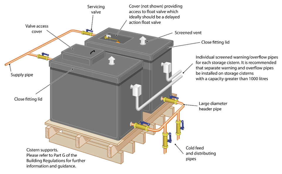
In addition to an inlet, outlet, overflow pipe and warning arrangement a cistern should have a rigid close fitting and securely fixed lid or cover. Cisterns, and their lids, should be made of materials which do not shatter or fragment when broken.
An inlet valve must be fitted. This should be securely and rigidly fixed and must shut off the flow at a set level within the cistern. Typically, this level is a minimum of 25 mm below the overflow but should be increased to a minimum of 50 mm if there is no warning pipe. Where a float operated valve is to be used, this must be capable of being adjusted to ensure that the inlet valve closes at a defined level.
Where the inlet forms part of an air gap arrangement intended to prevent backflow, the inlet valve should not come into contact with the contents of the cistern as a result of splashing or foaming. If this occurs the inlet valve should be adjusted to increase the air gap.
Float operated valves are generally, but not always used for controlling the flow of water into a cistern. Electrically or pneumatically operated valves are also an acceptable form of valve for controlling the inlet flow. In all cases the method of installation must be suitable for the specific installation and comply with all aspects of the appropriate water fittings regulations/byelaws.
Transient pressure increases or surges (water hammer) may be caused by the rapid closure of valves, resulting in a sudden stop or change of water flow. To keep pressure surges within reasonable limits and prevent damage to water fittings hydro-pneumatic accumulators, surge arrestors or pressure reducing valve can be installed.
In addition to any backflow protection required by the local water undertaker a servicing valve must be installed on the inlet adjacent to the cistern and outlet to facilitate maintenance and minimise waste.
To encourage mixing and prevent areas of stagnation or ‘short circuiting’ within the cistern where practical the cistern inlet and outlet should be on opposite sides of an appropriately sized cistern. Where multiple cisterns are linked; inlets and outlets need to be carefully balanced to promote a good turnover of water in each cistern.
Where practicable all outlets from a storage cistern should be located at the bottom of the cistern and to encourage mixing and prevent areas of stagnation or ‘short circuiting’ within the cistern on the opposite side to the inlet.
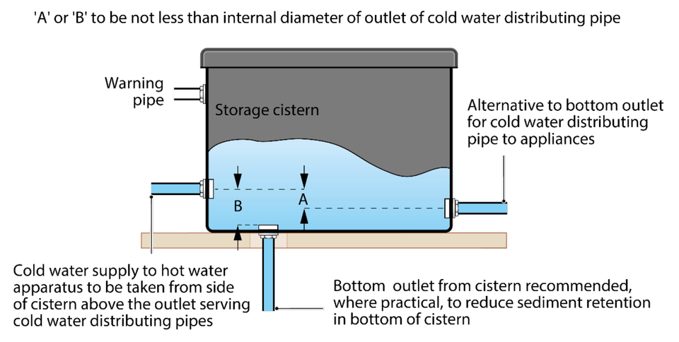
All outlets from cold water storage cisterns, except vent pipes, overflow pipes and warning pipes, should be fitted with a servicing valve as close to the cistern as is reasonably practicable.
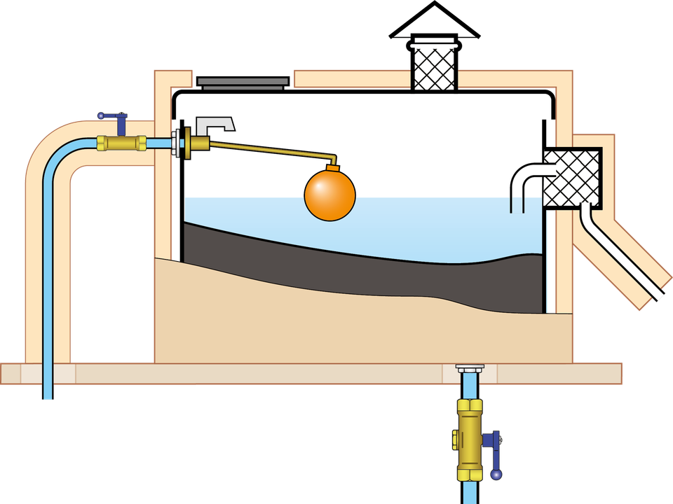
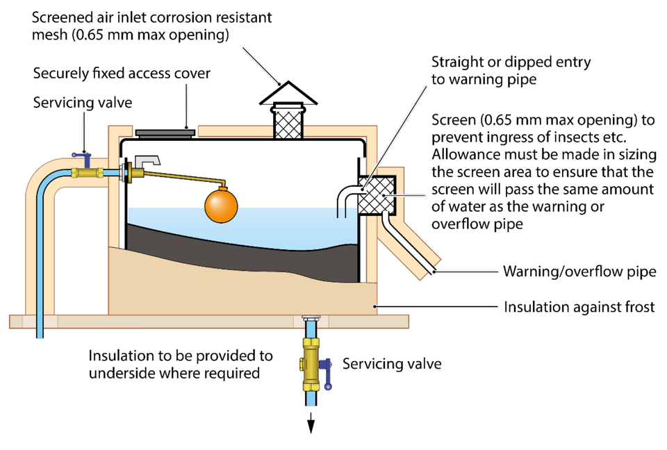
Every cold water storage cistern must be fitted with an overflow pipe.
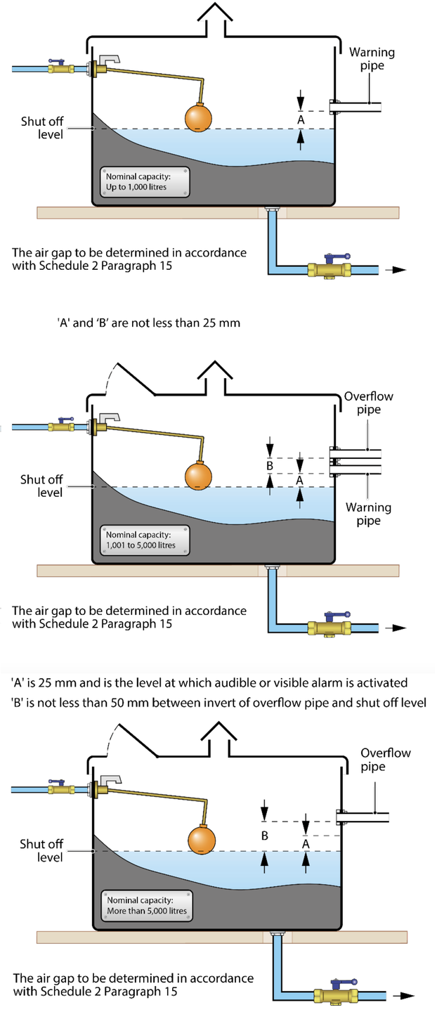
To help minimise waste a suitable means of warning of an impending overflow must also be installed. A warning pipe is commonly used for this purpose, but with the local water undertaker’s agreement alternatives may be fitted. Although usually separate a combined overflow/warning pipe may be accepted on cisterns with a capacity of 1,000 litres or less.
Overflow and warning pipes must be positioned so as to exclude light and insects. A screen with a mesh size no greater than 0.65 mm (opening) is typically used to prevent the ingress of insects and other foreign bodies. If an insect screen is installed it should be vertically and removable.
Overflow and warning pipes should be installed on a downward inclined plane and not discharge into any other cistern.
The discharge from the overflow and/or warning pipe should be safe and conspicuous. If discharging to drain a visible air brake, giving fluid category 5 backflow protection in the form of an air break to drain conforming to the design specification given in EN 1717 must be installed.
If a common warning pipe is used the location of the cistern overflowing must be readily identifiable. A warning/overflow pipe should be at least 19 mm (internal diameter) and capable of accommodating all possible flow rates i.e. the maximum inflow under fault conditions. The effect of any screen on the nominal flow capacity must be taken into account when determining the size of an overflow.
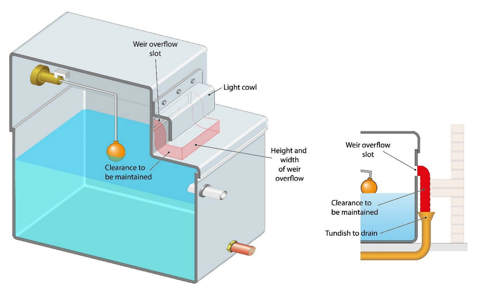
A cold water storage cistern can sometime incorporate a Type AB air gap. Where this is the case it is important to minimise any light penetration through the weir overflow. This is because light is known to promote the growth of algae which could lead to not only taste and odour concerns but also provide nutrients which could support the growth of bacteria. The most common way of addressing this issue is to fit a cowl or shroud that covers the weir slot.
To demonstrate the cowl or shroud arrangement does not impede any discharge it should mirror the overflow weir in size and shape to at least below the lowest point of the weir and any surfaces below or to the side of the cistern as shown below. Information can also be found here
Please note: cold water storage cisterns incorporating a Type AB air gap are sometimes being used as backflow protection arrangements for high risk installation downstream and should not be removed or altered without the agreement of the local water undertaker.
Factors to consider when deciding where and how cold water storage cisterns are installed include but are not limited to:
whether the distributing pipework (system) is pumped or supplied by gravity
the need to allow for ease of access for maintenance • inspection (both internally and externally)
cleaning requirements
environmental factors which might affect water quality such as excessive heat gain or the likelihood of flooding.
Float operated valves and other controls should be readily accessible. There should be sufficient clearance to allow for inspection, cleaning of internal surfaces and maintenance.
Cisterns with a capacity greater than 1,000 litres should be capable of being inspected and cleansed without having to be wholly uncovered.
To avoid distortion cold water storage cisterns should be adequately supported. Advice on how to do this can be found in Part G of the Building Regulations.
Please note: In many cases the local water undertaker will need to be given advanced notice of the proposed installation of any cold water cistern. This is an important simple and essential check to minimise the risk to water supplies.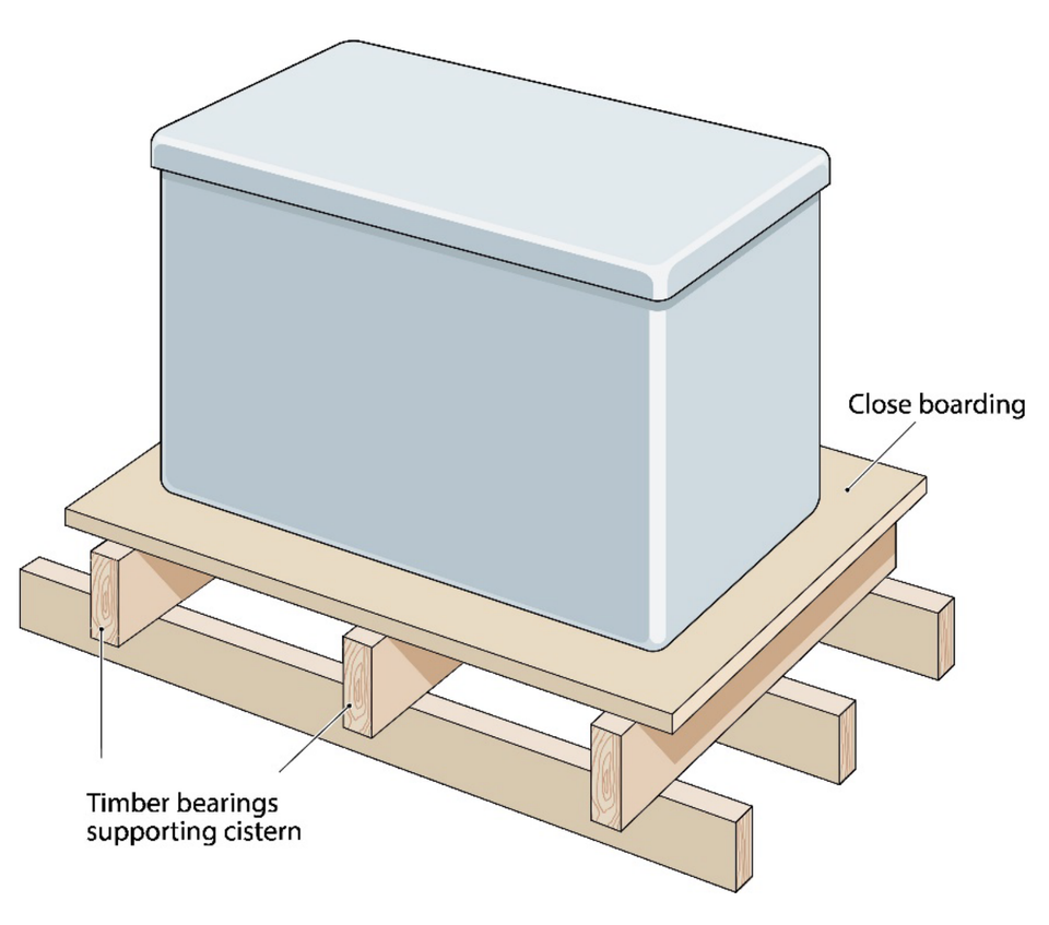
Due to concerns about water stagnation which might cause the quality of the water to deteriorate the installation of inter-linked storage cisterns should be avoided wherever possible. Where it is unavoidable, the number of inter-linked cisterns should be minimised.
To minimise the risk of stagnation:
The storage volume should be kept to a minimum
Cisterns should be connected in parallel
Any demand should create water flow throughout each cistern
Inlet and outlets should be installed at opposite ends of the cistern
Delayed action float valves should be used
Metering of inlets may assist with balancing of turnover
To minimise the risk of damage due to freezing all cold water storage cisterns, including any associated pipework which may be at risk, should be protected. The type and level of protection will be dependent on the environment in which the installation is located.
In premises where there will be water demand or a positive change to the ambient temperature within 12 hours, the insulator calculator can be used to give an indication of insulation requirements. Where this is not likely to be the case the local water undertaker should be consulted as insulation alone may not be suitable.
Undue warming is of concern for two reasons. It can potentially cause a deterioration of water quality and often result in customers leaving taps to run to waste.
Cold water storage cisterns and associated pipework should be sited away from heat sources and insulated.
Systems supplying cold water should be ideally designed to ensure that they distribute water at temperatures no greater than 20°C. This requirement may also apply under other legislation and code of practices, such as those relating to legionella control.
Good system design, commissioning and maintenance will help to reduce and address the risk of contamination resulting from microbial growth and limit waste due to taps left to run.
Storage and distribution temperature requirement for domestic hot water systems are set out in other legislation, codes of practice and British Standards.
For further information please refer to Building Regulations, BS EN 806, BS 8558, HSC L8 and CIBSE Commissioning Code M.
The risk is dependent upon the fluid, the dose used and concentration within the system. The volume of fluids and operating pressures will also be considered when assessing the suitability of the backflow protection device or arrangement to be installed.
Please note the final decision rests with the local water undertaker.
Yes, appropriate separation is required. Minimising the risk of contaminated fluids coming into contact with water to be used for domestic purposes (drinking, bathing, washing, cooking etc) is a key objective of the water fittings regulations/byelaws.
Mindful of the need to ensure sufficient safeguards are in place to address the possibility of drinking water supplies coming into contact with fluids which are not considered to be wholesome, in determining whether systems making use of heat recovery or exchange are compliant with regulation 4(1) the following factors will be taken into consideration. Please note decisions will be taken on a case by case basis.
The actual fluid categories of the fluids within the system.
How readily identifiable any potential integrity failure of the system would be.
Whether the system design meets the requirements for single or double wall separation specified in BS EN 1717.
Where a closed circuit (heating system etc) has been categorised by the water undertaker as a fluid category 3 risk, the installation of a compliant double check valve on the fill point connection to the supply/distribution pipe may be considered as acceptable backflow protection.
Where a fill point connection incorporates a “flexible connection”, when not in use it is good practice for the hose to be completely disconnected and removed. However, a partial disconnection, that is to say only detaching one end of the hose, may be acceptable providing the disconnection is made between the hose and the backflow prevention device on the supply/distribution pipe.
Please note: if the water undertaker has concerns about the likelihood of contamination, or the suitability of a double check valve - for example due either to age, operating temperature or pressure fluctuations – under schedule 2 paragraph 15(4) they can require the installation of additional backflow protection. Further information about backflow protection can be found in the Guidance section on the Water Reg UK website.
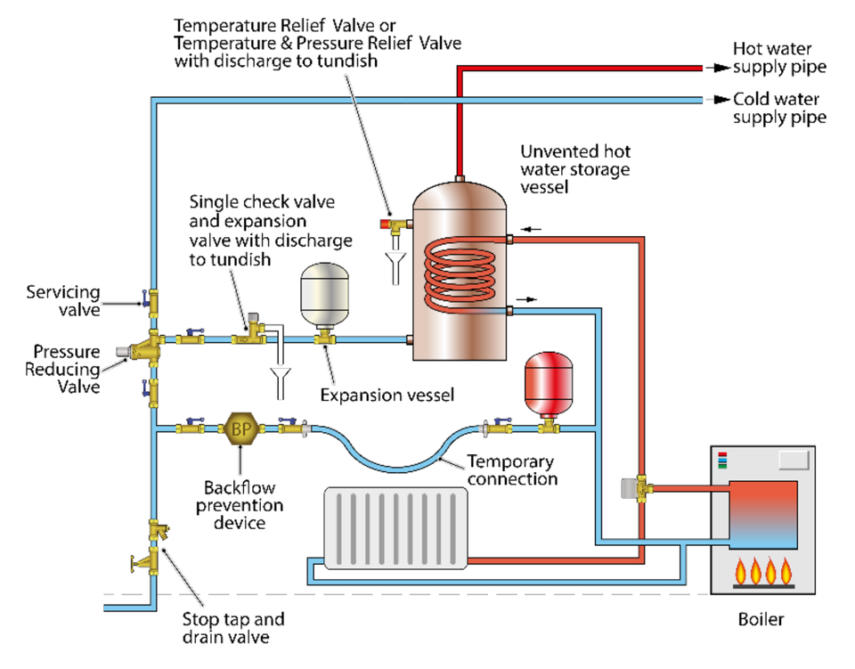
Acceptable safety devices include:
Temperature relief valves
Temperature control arrangements such as non-self-resetting energy cut outs and cylinder thermostats (interlocked to prevent flow from the primary circuit).
Combined temperature and pressure relief valves
Pressure reducing valves
Expansion vessels installed in combination with expansion relief valves. For further information, including advice about safety device arrangements for different methods of heating, please refer to the relevant version of the Building Regulations.
All safety devices must comply with the requirements of regulation 4(1). Examples of appropriate British Standards are given in the guidance to part G of the Building Regulations.
All water fittings must be suitable for the circumstances in which they are used. In addition to the normal system operating temperatures and pressures consideration should be given to the suitability of components for use at elevated temperatures likely to be encountered under fault conditions.
The safety arrangements installed on a water heater used to heat water for domestic applications should prevent the temperature exceeding 100o C.
The suitability of safety arrangements for other applications, for example industrial processes will be assessed on a case by case basis.
Where the source of heat energy cannot be relied upon in all circumstances to achieve the required minimum temperature to address concerns about microbiological growth an additional heat source should be available.
Any discharge from a hot water system safety device should be safe and conspicuous. Where a discharge is made via a tundish it should conform to the applicable British Standard or equivalent. For further information please refer to the relevant version of the Building Regulations.
Advice regarding the sizing of hot water system vent pipes can be found in the guidance to part G of the Building Regulations, BS EN 806 and BS 8558.
All hot water systems must be capable of accommodating expansion. There are various ways to do this including:
(a) Secondary hot water systems only
The water fittings regulations/byelaws permit accommodation within the secondary hot water system, of thermal expansion from unvented water heaters (with the exception of instantaneous water heaters with a capacity less than 15 litres).
This is however only allowed if:
The expanded water does not increase the temperature of the water in the supply pipe to in excess of 25°C in England and Wales 20°C in Scotland and Northern Ireland. As this may result in waste or impact on wholesomeness.
Both the expanded water plus any displacement can be accommodated within the supply pipe. It is not permissible for water displaced as a result of accommodating expansion to backflow into the pipework owned by the local water undertaker.
(b) Primary feed and expansion cisterns
To prevent waste the preset water level for expansion cisterns or combined feed and expansion cisterns should accommodate at least 4% of the total volume in the primary (heating) system circuit before discharging through the overflow or warning pipe.
(c) Expansion vessels
To address contamination concerns associated with stagnation and particulate accumulation it is recommended expansion vessels be installed so as to avoid localised low turnover (stagnation).
Specifically, they be installed securely in the vertical so that the water fitting is:
bottom fed and upright
the connecting pipework to the fitting
rises continuously
is kept to a minimum
sized correctly for the system
designed to ensure an adequate turnover of water within the expansion vessel.
Please note: Where an expansion vessel is used an expansion valve which operates at an appropriate operating pressure must be fitted to ensure water discharges safely and conspicuously in the event of a malfunction. To prevent waste the expansion valve must automatically close after a discharge.
No intervening valves should be installed between the expansion vessel, expansion valve and hot water heater/storage.
Protecting public health by minimising the risk of contaminated fluids coming into contact with water to be used for domestic purposes is a key objective of the water fittings regulations/byelaws. In keeping with this principle, where there is considered to be a contamination risk this is either mitigated by avoidance or safeguards such as installing backflow protection.
Depending upon their design and fluids involved, heating and cooling systems which make use of heat recovery or exchange, including but not limited to those listed below, pose different potential contamination risks.
Heat exchangers linking primary and secondary systems
Ground source and air source heat pumps
Chillers
Calorifiers
Heat recovery products utilising the heat energy in wastewater
In enforcing the regulations/byelaws water undertakers take a risk based and proportionate approach. Enforcement policies cite the need to be transparent, consistent, targeted and accountable.
Mindful of the need to ensure sufficient safeguards are in place to address the possibility of drinking water supplies coming into contact with fluids which are not considered to be wholesome, in determining whether water fittings/systems making use of heat recovery or exchange are compliant with regulation 4(1) the following factors will be taken into consideration. Please note decisions will be taken on a case by case basis.
The actual fluid categories of the fluids within the system.
How readily identifiable any potential integrity failure of the water fitting/system would be.
Whether the fitting design meets the requirements for single or double wall separation specified in BS EN 1717.
Please note: pipework supplying water for domestic use should be external to and separate from wastewater pipework. It should not be sealed within a fitting which conveys wastewater unless the local water undertaker has been notified and given consent.
The purpose of the water fittings regulations/byelaws is to prevent contamination, waste, misuse, undue consumption and erroneous measurement. There are a number of regulators responsible for enforcement of safety requirements including the Health and Safety Executive, Trading Standards and local authorities. Satisfying the water fittings regulations/byelaws does not guarantee compliance with the regulations these bodies enforce.
The method of support and spacing between supports will be dependent on the type of water fitting and material it is constructed from.
In the case of pipework allowance should be made to accommodate likely movement for example thermal expansion and contraction.
Useful sources of information include BS EN 806:4, and BS 8558.
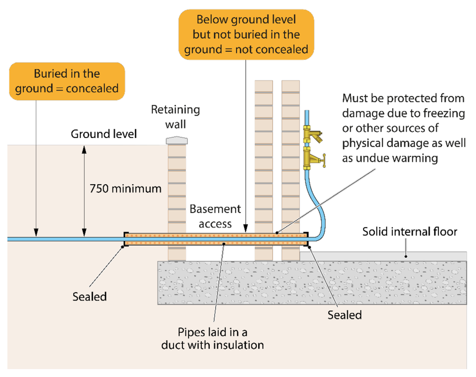
Water fittings considered to be concealed include those:
Buried in the ground
Installed below or embedded in floors
Installed in or behind wall finishes
Water fittings considered not to be concealed include those:
Installed below ground but not buried, such as in a chamber or basement room
Installed below floors or in walls which can be readily accessed
Joints on concealed pipework are likely to lose their integrity over time and therefore should only be considered where unavoidable.
To prevent waste there needs to be provision to access any joints or water fittings which require maintenance, such as backflow prevention devices, valves which control the flow and any other operational fitting.
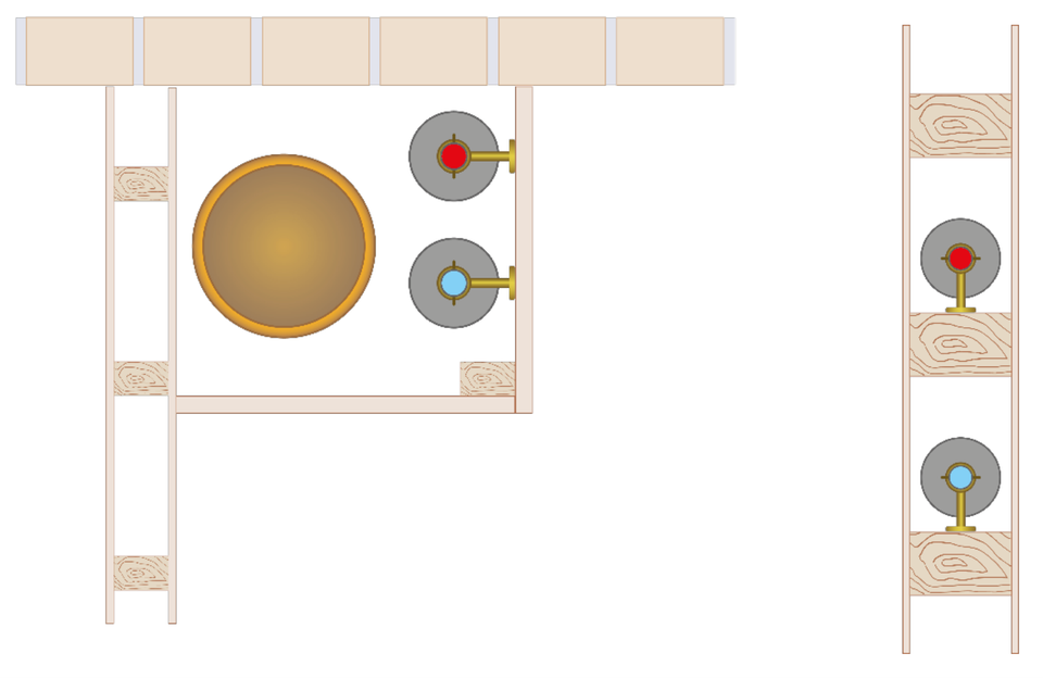
All domestic hot and cold water system pipework concealed within walls should:
Be installed with a minimum number of joints. This is because joints are prone to a loss of integrity over time and therefore should only be considered where unavoidable.
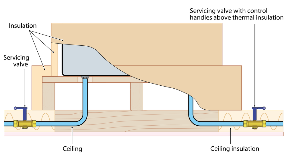
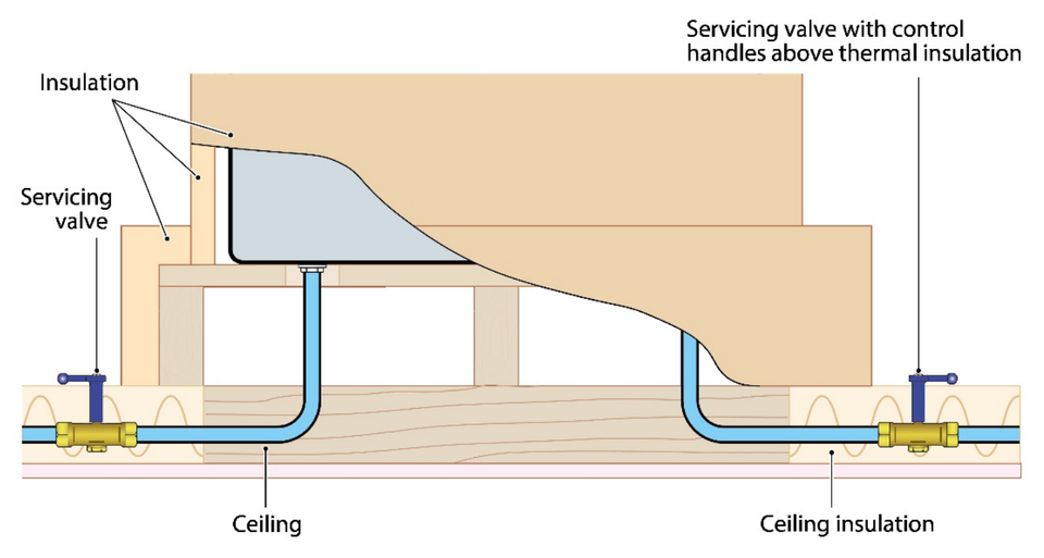
Be installed in a chase/duct or void. Wrapping pipework in insulation is not an acceptable method of ducting or passing through a chimney is not an acceptable method of ducting.
With the agreement of the local water undertaker pipework may be installed alongside other services in a shared duct. An example of what may be considered as acceptable is shown below.
Be appropriately clipped to avoid water hammer and other stresses which would affect the integrity of the installation.
Be insulated with a suitable gap maintained between the cold water, hot water and any other heat source to prevent heat transfer or loss.
Not be embedded or come into contact with other materials such as plaster or cement.
Be accessible to enable inspection and replacement. Further information about accessibility can be found in BS 8558.
Below are images illustrating domestic hot and cold water systems concealed in a wall and a soil pipe duct.
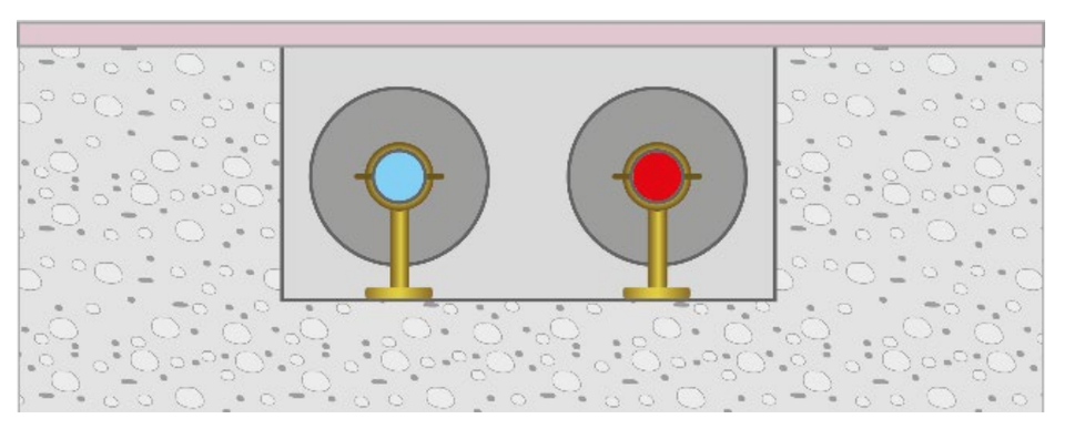
All domestic hot and cold water system pipework concealed within floors should:
Be installed with a minimum number of joints. This is because joints are prone to a loss of integrity over time and therefore should only be considered where unavoidable.
Be installed in a chase/duct or void. Wrapping pipework in insulation is not an acceptable method of ducting.
Be appropriately clipped to avoid water hammer and other stresses which would affect the integrity of the installation.
Be insulated with a suitable gap maintained between the cold water, hot water and any other heat source to prevent heat transfer or loss.
Not embedded or come into contact with other materials such as backfill, screed or cement.
Be accessible to enable inspection and replacement. Further information about accessibility can be found in BS 8558.
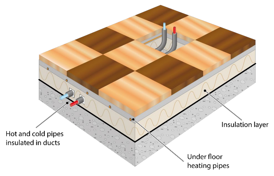
Underfloor heating systems should be installed in a manner considered to be acceptable to building control and the local water undertaker.
If domestic supplies are to be installed in close proximity to underfloor heating, they should:
Be installed as a single run of pipework without any inaccessible joints below the underfloor heating insulation.
To prevent heat transfer or loss any supply pipework should be laid with a suitable gap maintained between the hot and cold systems and both wrapped in insulation.
Firstly, the pipe and fittings, including method of connection, should be suitable for below ground use and the environment in which they are to be installed. Joints should be kept to a minimum. Water fittings which are susceptible to permeation by hydrocarbons should not be laid in ground near installation storing or ground contaminated with petrol or oil unless protected.
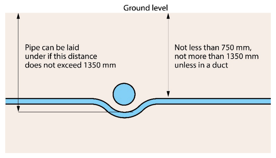
Pipework should be laid at a depth of not less than 750 mm (to limit the effect of freezing and mechanical damage) and no greater than 1350 mm deep. They should be embedded in nonabrasive materials. Where this cannot be achieved in all circumstances the consent of the local water undertakers must be obtained via notification.
Where the local water undertaker consents to pipework being laid at less than 750 mm it should be installed as deep as possible below ground level and protected against warming, freezing and mechanical damage (for example due to ground movement).
Pipework should not be installed above ground level is not permitted without the agreement of the local water undertaker.

Examples of how to avoid below ground obstructions are given below. Please note the local water undertaker should be consulted before laying pipework over an obstruction.
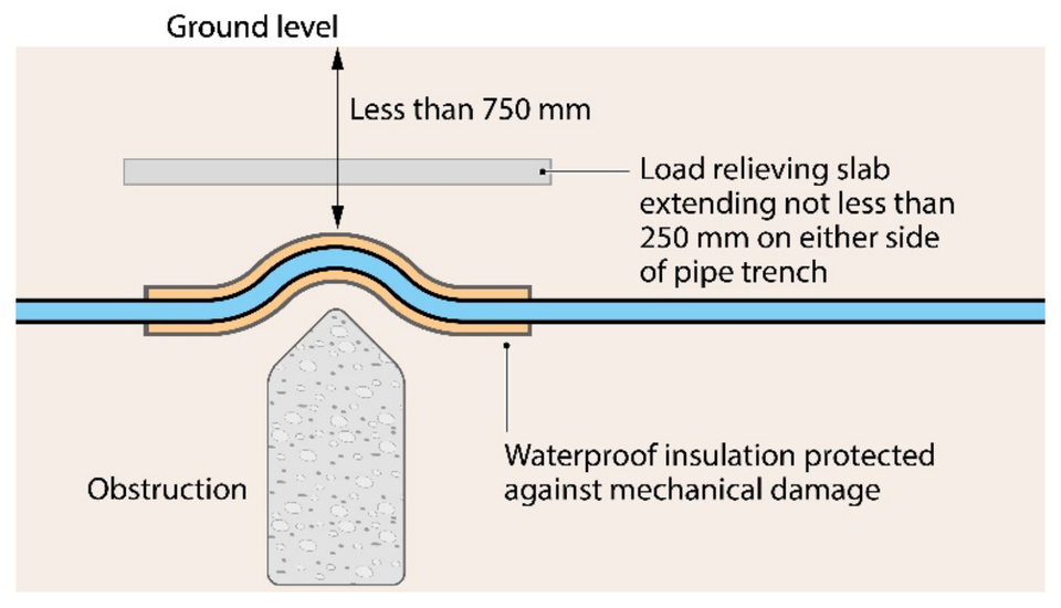
Pipework should never be installed in a contaminated environment such as a sewer or cesspool.
Non-metallic (plastic) plumbing fittings are at risk of permeation by diesel or heating fuel, pesticides, insecticides and similar organic substances or fluids, so should never be installed where they could come into direct contact, including contact with soil contaminated with them.
Where this is unavoidable contact the local water undertaker for advice.
Non-metallic water fittings which are susceptible to permeation should not be installed in close proximity to other services for example gas pipelines, or in ground contaminated with hydrocarbons or other contaminants of concern.
For further advice contact the local water undertaker.
The recommended distances between utilities can be found in the latest National Joint Utilities Group (NJUG) guidelines. Where these dimensions and depths cannot be achieved protective measures will be required.
If the installation of the pipework is notifiable, under regulation 5 of the water fittings regulations in England, Wales and Northern Ireland, byelaws in Scotland, installation advice should be provided as part of the notification process.
If it is not notifiable there remains a legal obligation for the premises owner or occupier to ensure the plumbing work is fully compliant with the water fittings regulations, byelaws in Scotland.
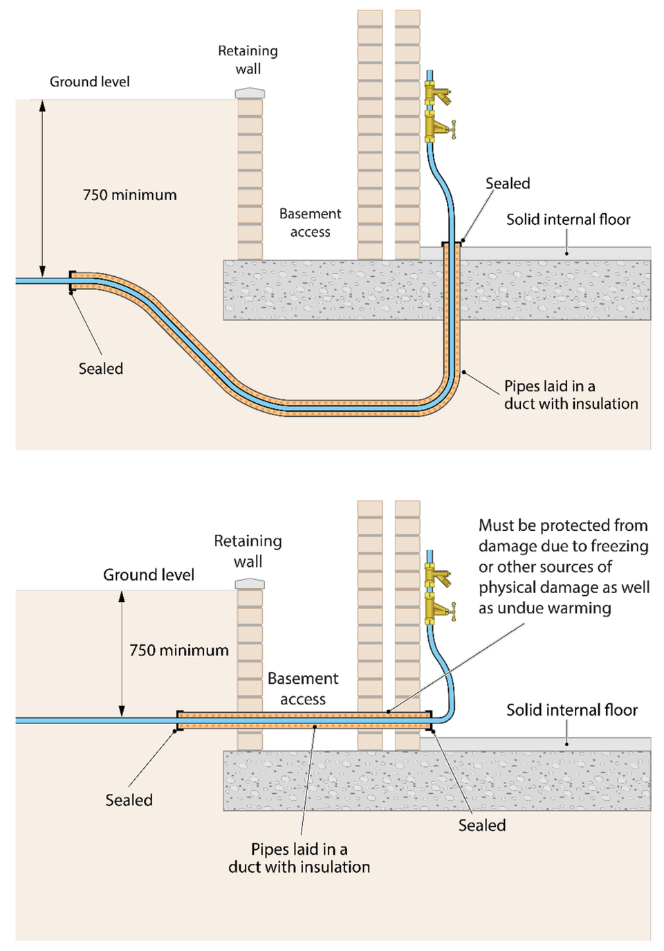
The supply pipe to a building should enter at a depth of 750 mm.
Pipework passing through walls and laid at depths of less than 750 mm, including any inside the building should be ducted. This is to prevent damage and facilitate ease of replacement, the internal surface of the ducting should be smooth bore i.e. any ridging to be external only.
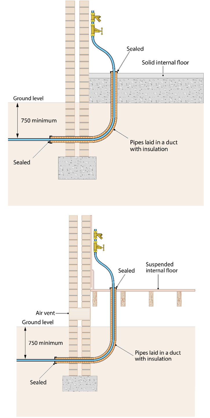
The pipework should be sealed using a method acceptable to the local water undertaker. This is to prevent ingress of gases and vermin. It should also be adequately insulated. Where pipework is installed below a suspended floor if there is an air vent the pipework should be ducted and insulated to the finished floor level.
In premises where there will be no water demand or a positive change to the ambient temperature after 12 hours, the insulator calculator can be used to give an indication of insulation requirements. Where this is not likely to be the case the local water undertaker should be consulted as insulation alone may not be suitable. Example of pipework entering a building at and below street level are given below.
In addition to the requirements already listed, above ground plumbing must be protected against environmental conditions, accidental, mechanical and animal damage.
A regular inspection should be undertaken of pipework and water fittings to identify leaks or other issues. This will help to reduce waste, prevent contamination and save cost.
The type and level of frost protection required will depend upon the environment in which a water fitting is installed, with insulation and trace heating commonly used.
Any water fitting installed outside the thermal envelope or at depths of less than 750 mm should be protected against damage caused by freezing.
Any not used during cold weather, such as seasonal irrigation systems should be isolated and drained down. Similarly, if a premises is to be left unoccupied and unheated during cold weather, for example a holiday home or caravan, the water supply should be turned off and plumbing system drained.
When installed in accordance with the manufacturer’s instructions insulation may delay but not prevent freezing.
Providing within 12 hours the plumbing system is used (there is demand flow) or there is an increase in the ambient temperature, the insulator calculator can be used to give an indication of insulation requirements for installations exposed to low temperatures. Where this is not likely to be the case the local water undertaker should be consulted as insulation alone may not be suitable.
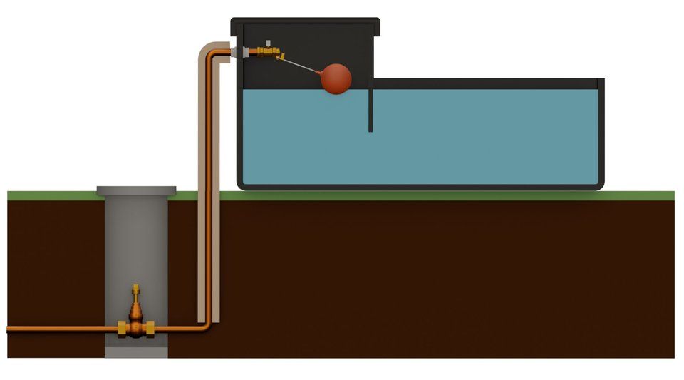
Information on installing underground water storage which is
Supplied directly from mains
Installed below ground level, wholly or partially outside the thermal envelope
can be found in the Underground Storage Guidance booklet
The image below is to be used in conjunction with this document.
Information on installing wastewater and chemical emptying points can be found in the the Camping sites, caravan holiday parks and residential park home estates booklet.
The image below is to be used in conjunction with this document.
If water is supplied for drinking, cooking, bathing or washing (domestic use) a drinking water tap must be installed. Where possible this should be supplied direct from mains i.e. not via any water fitting which stores, treats or filters the water.
It is recommended where possible drinking water taps be connected directly to the incoming mains water supply. Where this is not feasible, they can be fed from a storage cistern or pumped, but wholesomeness must be maintained, meaning the water fittings used must not adversely affect water quality.
Any tap supplying water which is not wholesome must be labelled in accordance with BS 1710. In non-household premises it is recommended all taps are labelled to help users to distinguish between sources of drinking and non-drinking water.
Yes, as long as it’s of an appropriate quality and standard. Please note if the softened or conditioned water is to be used for drinking, cooking, bathing or washing (domestic purposes) then it must remain wholesome i.e. satisfy water quality requirements.
A self-closing tap is one which turns itself off automatically after a set time or volume of water has been discharged, for example non-concussive and infrared taps often used to save water or in areas where taps are prone to being left open.
Wholesomeness is defined in water quality regulations (England & Wales, Scotland and Northern Ireland). To be considered as wholesome water must:
Meet all the prescribed standards set out in the relevant version of the water quality regulations.
Be aesthetically acceptable to customers in terms of appearance, taste and odour.
Not contain anything, either alone or in combination, which may be harmful to health.
If the installation of a multifunction tap is notifiable, under regulation 5 of the water fittings regulations in England, Wales and Northern Ireland, byelaws in Scotland, installation advice should be provided as part of the notification process.
If the installation is not notifiable there remains a legal obligation for the premises owner or occupier to ensure the plumbing work is fully compliant with the water fittings regulations, byelaws in Scotland. To assist installers water undertakers and Water Regs UK publish installation guidance on a range of topics including multifunction taps.
If there are any further questions, please contact the local water undertaker for advice.
Overtime minute traces of copper (which is an essential element that naturally occurs in water) become trapped within plastic materials used to manufacture a kettle. When these traces then comes into contact with oxygen inside the kettle they undergoes a process called oxidation, turning them black.
It can be washed out using a weak acid solution, such as a kettle descaler, readily available in most supermarkets and online retailers. These are not harmful when used in accordance with the manufacturer’s instructions.
There are normally two reasons why water may appear cloudy, both are usually harmless.
The most common reason is minute bubbles of air trapped in the water. These air bubbles are so small that they are not readily visible to the naked eye and customers often describe this as their water having a ‘white cloudy’, 'milky' or ‘chalky’ appearance.
Air bubbles in the water may be caused by for a number of reasons:
A loose or worn tap washer, this is usually accompanied by a distinctive ‘singing’ sound from the tap at certain flow rates.
A sudden reduction in pressure (because of opening the tap) which can release air dissolved in the water, in the same way as dissolved carbon dioxide is released when a bottle or can of fizzy drink is opened. This can be confirmed by filling a clear glass with water and checking to see if the cloudiness clears from the bottom to the top of the glass.
Maintenance work on your plumbing installation may cause air to become trapped within the system, especially if your water supply was turned off temporarily during the work.
If your hot water pipes run too close to your cold water pipes.
Another cause of white/cloudy water can be small particles in the water. These particles may have become dislodged from pipework or other water fittings within the property, becoming suspended in the water giving it a white cloudy/opaque appearance.When a glass is filled any such particles would slowly sink, leaving chalk like deposits at the bottom of the glass.
In both cases, leaving your taps running at a gentle steady flow for a short period should resolve these issues.
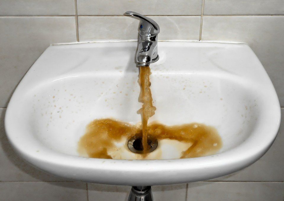
When iron deposits become re-suspended, they can react with the oxygen in the water which can result in it becoming yellow in appearance, this is generally harmless. This discoloration can be caused by a disturbance in the main, such as a burst, or a cast iron pipe (typically used in the 1950’s and 1960’s) coming to the end of its life. In the case of the latter the yellow discoloration may also be accompanied by brown or black flecked particles. This may be as a result of a change in flow pressure (such as following a burst pipe or excessive supply demand) disturbing harmless deposits within the pipework.
If the water has a bright or fluorescent yellow colour, contact your water undertaker.
Clean water will naturally have a blue hue to it. Water which has a definite blue or turquoise colour as opposed to hint, is often due to new copper pipe work or the use of poor quality brass fittings. To help prevent this from happening new pipe work needs to be thoroughly flushed, which may need to be repeated over a period of weeks until the pipework stabilises, and make sure brass fittings are manufactured from appropriate materials.
Another source of intense blue water may be water siphoned back via inlet valves supplying toilet cisterns. Where the inlet to toilet cisterns is installed incorrectly water coloured by a toilet block (the colour of the water will depend on the colour of the toilet block used, if this is the issue) can be back siphoned into the plumbing system.
If you suspect you have elevated level of copper or water back siphoned from a toilet block, please contact your water undertaker for advice.
If your water has a rancid or rotten odour or taste, then it is important to determine the source of the supply. If it is fed from a storage cistern this should be inspected for any signs of any animals or birds having gained access.
Where evidence of animal or bird activity (access into the cistern) is found the storage cistern plus any associated pipework arrangements should be drained, cleaned and thoroughly disinfected.
If the supply is direct from the main, then contact the water undertaker immediately. They will be able to provide further help and advice.
Sometimes a sewage or stagnant type smell can emanate from a sink or plug hole, especially if the water draining away is warm. This indicates a possible blockage or build-up of waste materials, making the drinking water appear as if it has an unpleasant smell. Filling a glass with water, taking it into a different room (away from the kitchen sink) and then smelling it, may help to determine whether the odour is genuinely from the water or not.
If the water still smells, please contact the water undertaker immediately.
Chlorine in drinking water is not harmful. It is added to drinking water as the final stage of treatment to protect public health. Water undertakers monitor chlorine concentrations closely to keep the levels as low as possible whilst keeping water supplies safe. Concentrations can vary throughout the day and year. They may be higher if you live close to a water treatment works.
Some people are sensitive to the taste and smell of chlorine. The taste of chlorine can be reduced by allowing it to stand in a closed container in a fridge until needed. If this does not work, try boiling the water for about five minutes before storing it. This should remove most of the chlorine. If not drunk within 24 hours, it should be used for purposes.
Home treatment devices like a water filter, are generally not necessary but some customers like to use them. These typically make use of activated carbon to absorb chlorine and other substances which can influence the taste of the water. Please note water treatment devices must be of an appropriate quality and standard. If not properly maintained, they may cause water quality problems.
A chlorine or metallic taste, especially in hot drinks, may not be due to the presence of chlorine. Instead, it is more likely to be associated with non-metallic plumbing materials, such as rubber washers, or hoses if you have appliances (such as vending machines, dishwashers, washing machines and garden hoses) plumbed in close to taps used for drinking water. The plasticiser in these products combines with the residual chlorine in drinking water, and when heated forms antiseptic/TCP tasting compounds when are most noticable in tea and coffee.
In the case of appliances this can be remedied by either changing the hoses for ones which are compliant with BS 6920 or installing a double check valve on the supply to the appliance. Garden hoses should always be disconnected from the hose union tap when not in use and should ideally be fitted with a trigger release gun for when in use.
There are a number of organisms which can cause a musty/earthy taste or smell in water that can grow inside taps. These are generally harmless.
If you notice this smell or taste, try using a mild household disinfectant to wash outside and inside your tap then running it a little before you use it again to rinse out the disinfectant.
If you have done this but are still concerned contact your water undertaker.
If there is a taste or odour of petrol or diesel to the water from your kitchen tap, please contact your water undertaker straight away and do not drink the water or use it for cooking purposes until you have sought their advice.
The most common cause of this issue are leaks or the spillage of hydrocarbons (the chemical compounds found within fuel and similar products).The water undertaker will want to know whether you have had any work done at the property (for example on the heating system), if you have any oil storage tanks or have recently had any oil spills at the premises (for example a car or motorbike leaking oil).
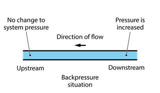
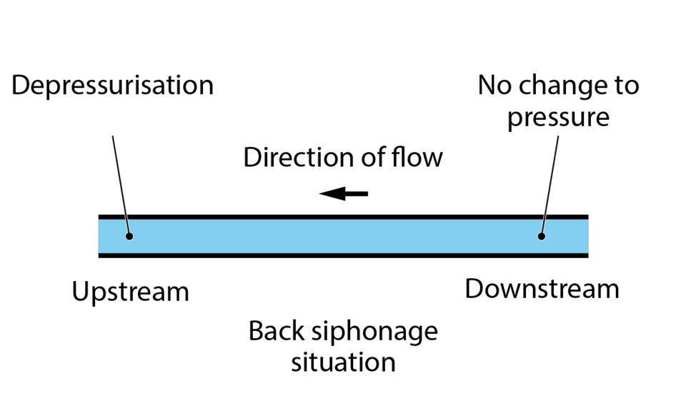
Backflow occurs when fluid flows in the opposite to the intended or normal direction of flow. There are two types of backflow, back pressure and back siphonage.

Backpressure: occurs when the pressure downstream increases above that of the supply pressure, in effect pushing fluids backwards against the intended or normal direction of flow.
Back siphonage: occurs when the supply pressure drops below that of the system it is supplying creating a depressurisation or vacuum which pulls fluids backwards against the intended or normal direction of flow.
The type of backflow risk is dependent upon a number of factors. Good design and the installation of suitable backflow prevention arrangements are key to avoiding backflow, which is why notification is so important.
As the circumstances which could lead to backflow are a common occurrence across the UK, contamination of public water supplies by backflow of fluids from customers premises is not theoretical. It is an ever present threat to water quality and public health.
As there have been a number of serious contamination events across the UK water undertakers take their role in preventing such incidents very seriously. Where infringements are suspected or identified they will act, not only to protect water quality and public health, but also to support owners and occupiers of premises to meet their legal obligations.
Where contamination incidents occur, it is likely that enforcement action, including criminal proceedings, will be taken against those who fail to meet their legal obligations.
Water undertakers are legally required to ensure the drinking water they supply is wholesome. Contamination occurs when there is a change in water quality irrespective of whether or not it is harmful to health
Schedule 1 of the water fittings regulations in England, Wales and Northern Ireland, byelaws in Scotland, classify the health risk posed by potential contaminants using a scale called fluid categories.
There are five fluid categories in total the lowest being 1 no risk the highest 5 a serious health hazard.

Fluid Category | Description | Example |
1
|
Wholesome (drinking) water supplied by the undertaker
|
water direct from a water undertaker’s main
|
2
|
Wholesome (drinking) water which has been changed either heated or altered in taste, odour or appearance
|
Hot water
|
3
|
Fluids posing a slight health hazard
|
low toxicity chemicals such as common disinfectants
|
4
|
Fluids posing a significant health hazard.
|
Toxic substances such as pesticides and environmental organisms
|
5
|
Fluids posing a serious health hazard
|
Pathogenic organisms, radioactive or very toxic substances such as faecal matter
|
As part of their statutory duty to enforce the water fittings regulations in England, Wales and Northern Ireland, byelaws in Scotland, the local water undertaker will identify the level of backflow protection needed. This categorisation will be based on a number of factors including the highest downstream fluid category risk the fitting is or is likely to be subject.
It is in effect a barrier intended to prevent contaminated fluid flowing backwards.
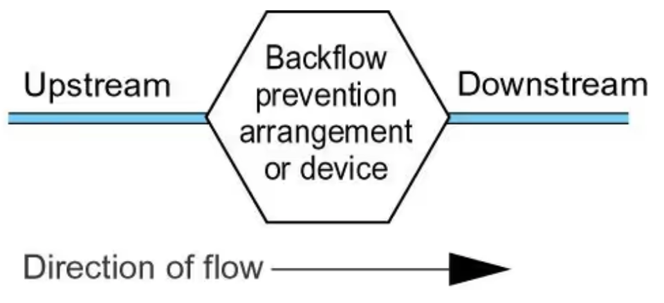
Schedule 2 paragraph 15 of the water fittings regulations in England, Wales and Northern Ireland, byelaws in Scotland require every plumbing system to incorporate protection against backflow. This is often referred to as point of use backflow protection. It can be provided by an air or tap gap arrangement or a mechanical backflow prevention device.
Backflow prevention arrangements and devices permitted under the regulations/byelaws need to be approved by the regulator or alternatively authorised as a relaxation. Relaxations allow a water undertaker the discretion to accept an arrangement as preventing backflow.
The regulator rates a backflow protection arrangement or device for suitability against contamination risk (fluid categories) and types of backflow risk - back siphonage or back pressure. They should always be accessible for inspection, maintenance and replacement.
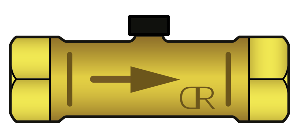
Backflow prevention devices, are required to be corrosion resistant. For example, for metallic backflow prevention devices manufactured of gunmetal or other dezincification resistant materials. Dezincification water fittings are typically marked with a CR symbol.
Wherever practicable plumbing systems should be protected against backflow without the necessity to rely on mechanical backflow protection devices.
A Type AA air gap is a non-mechanical backflow prevention arrangement comprising of an inlet which discharges water into a cistern, vessel, fitting or appliance (receiving vessel) and an outlet. Depending on the outcome of an assessment by the local water undertaker it can feed a single or multiple installations.
A Type AA air gap is rated by the Regulators as suitable backflow protection against both back siphonage and back pressure at the highest level of contamination risk, fluid category 5.
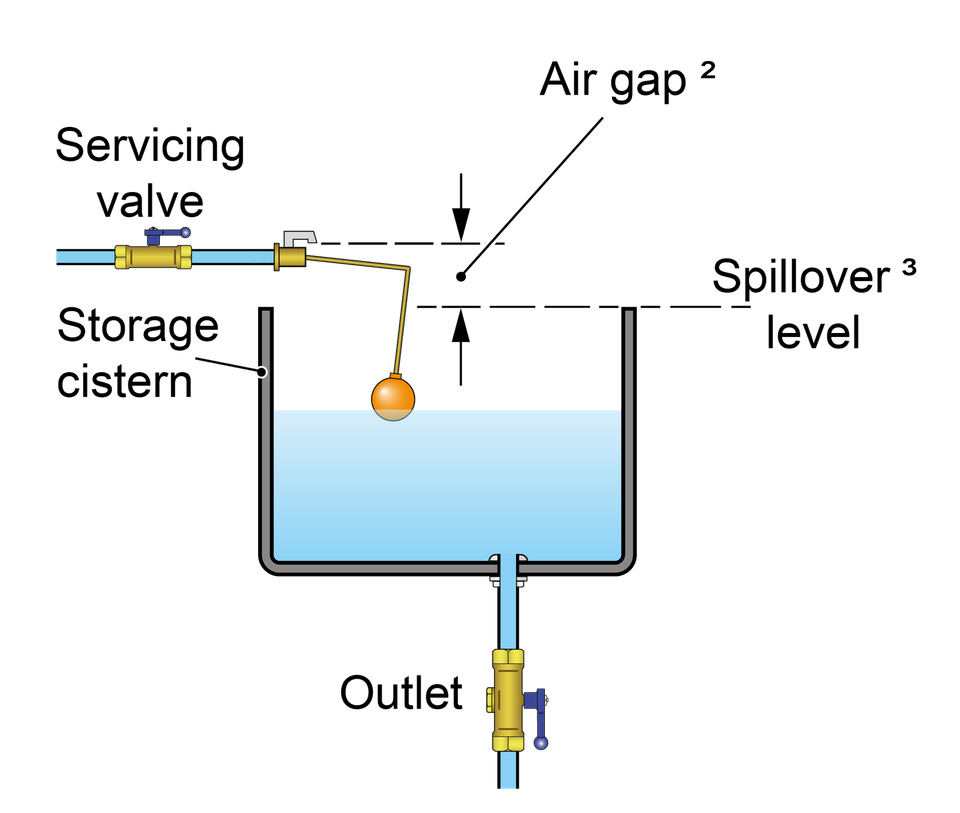
A summary of some of the key requirements for a Type AA air gap is given below:
The supply pipe and inlet control must be external to the receiving vessel and fixed so the air gap is maintained and unrestricted.
The air gap is an unobstructed and complete physical break between the lowest point of discharge and the spillover level of the contents of the receiving vessel. Measured vertically it must be no less than 20 mm or twice the internal diameter of the supply whichever is the greater.
The spillover level is the level at which the contents of receiving vessel spill over the top edge when the inflow of water exceeds the outflow through the outlet i.e. demand.
The spillover is unrestricted.
If the supply pipe feeding the inlet or the inlet itself comes into contact with the contents of the receiving vessel, for example due to splashing or foaming, then the air gap is considered to be compromised and must be increased to the point no contact occurs.
Type AA air gaps should be inspected, and as necessary, maintained every 6 months (BS EN 806: 5)
A Type AB air gap is a non-mechanical backflow prevention arrangement comprising of an inlet which discharges water into a cistern, vessel, fitting or appliance (receiving vessel) fitted with an outlet and a rectangular weir or ‘slot’ overflow. Depending on the outcome of an assessment by the local water undertaker it can feed a single or multiple installations.
A Type AB air gap is rated by the Regulators as suitable backflow protection against both back siphonage and back pressure at the highest level of contamination risk, fluid category 5.
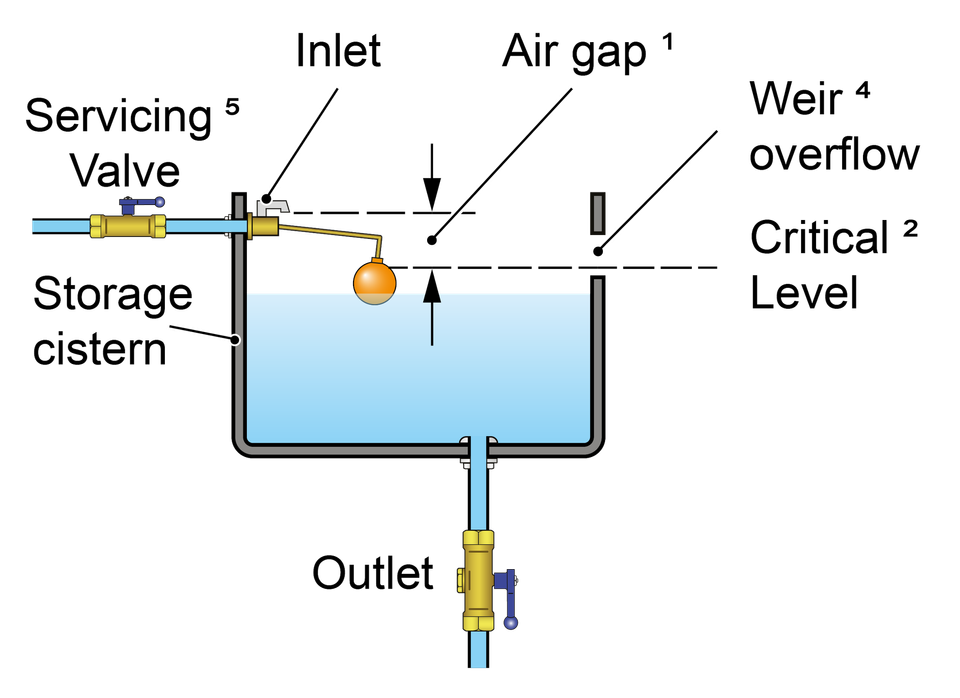
A summary of some of the key requirements applicable to a Type AB air gap is given below:
The air gap is an unobstructed and complete physical break between the lowest point of discharge and the critical water level of the weir overflow. Measured vertically it must be no less than 20 mm or twice the internal diameter of the supply whichever is the greater.
The critical level (sometimes referred to as h) is the fluid level in the receiving vessel under fault conditions i.e. when the outlet is closed but the inlet continues to discharge. It is measured at least 2 seconds after closing the water inlet
Whether sited internally or externally (as shown in the diagram opposite) the weir overflow must be rectangular (non-circular) and capable of accommodating discharge under fault conditions. Where a screened mesh is installed consideration should be given to the impact this may have on discharge flow. The air gap can be confirmed by test or calculation using the Type AB air gap calculator.
Neither the fluid pathway to the overflow nor the discharge from it should be restricted. For example, there should be a sufficient gap between the overflow and any surface to accommodate full discharge unimpeded during fault conditions.
Submerged supply pipes are not permitted. If the supply pipe feeding the inlet or the inlet itself comes into contact with the contents of the receiving vessel, for example due to splashing or foaming, then the air gap is considered to be compromised and must be increased to the point no contact occurs.
Type AB air gap installations, including screened mesh, should be inspected, cleaned and as necessary maintained every 6 months (BS EN 806: 5)
A Type AC air gap is a non-mechanical backflow prevention arrangement comprising of a vented, but submerged inlet that discharges into a cistern, vessel, fitting or appliance fitted (receiving vessel) with an outlet and circular overflow.
A Type AC air gap is rated by the Regulators as suitable backflow protection against both back siphonage and back pressure for contamination risks no greater than fluid category 3 .
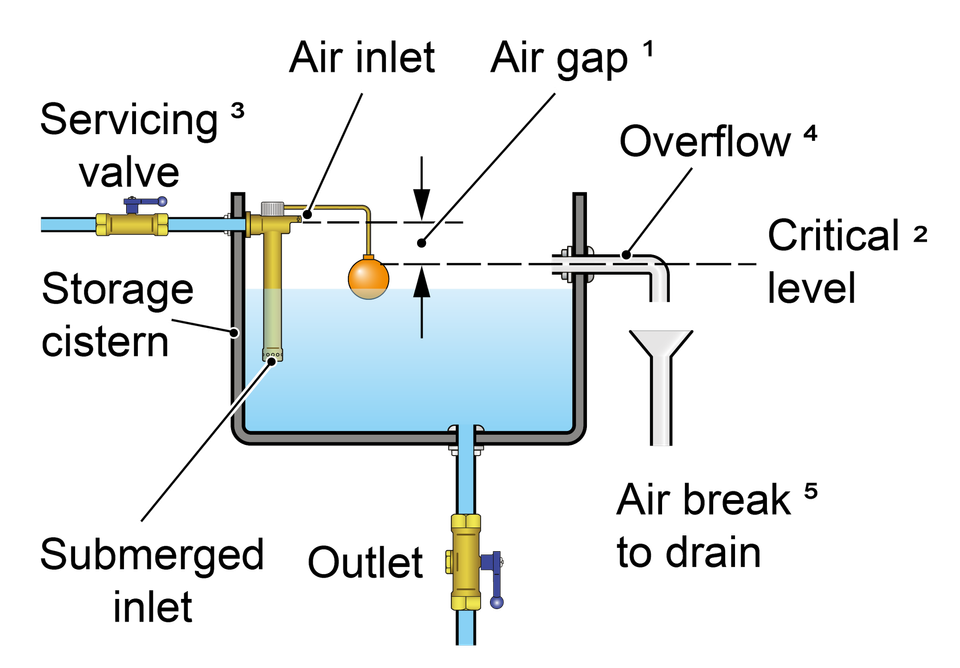
A summary of some of the key requirements applicable to a Type AC air gap is given below:
The air gap is an unobstructed and complete physical break between the lowest point of the vent (air inlet) and the critical water level of the weir overflow. It must be no less than 20 mm or twice the internal diameter of the supply whichever is the greater.
The critical level is the fluid level in the receiving vessel under fault conditions i.e. when the outlet is closed but the inlet continues to discharge. It is measured at least 2 seconds after closing the water inlet.
Supply pipes maybe submerged but adjustable or dismantlable joints on the are not permitted below the critical water level.
The overflow shall be not less than 19mm (internal diameter).
Where they discharge to drain the overflow and warning pipe must be fitted with an air break to drain or equivalent prior to the drain connection.
Type AC air gap installations should be inspected, and as necessary maintained every 12 months (BS EN 806: 5)
A Type AD air gap, sometime call a ‘jump jet’ is a non-mechanical backflow prevention arrangement comprising of a horizontal injector which ‘jets’ water into a cistern, vessel, fitting or appliance fitted (receiving vessel) and an air break to drain open to atmosphere.
A Type AD is rated by the Regulators as suitable backflow protection against both back siphonage and back pressure at the highest level of contamination risk, fluid category 5.
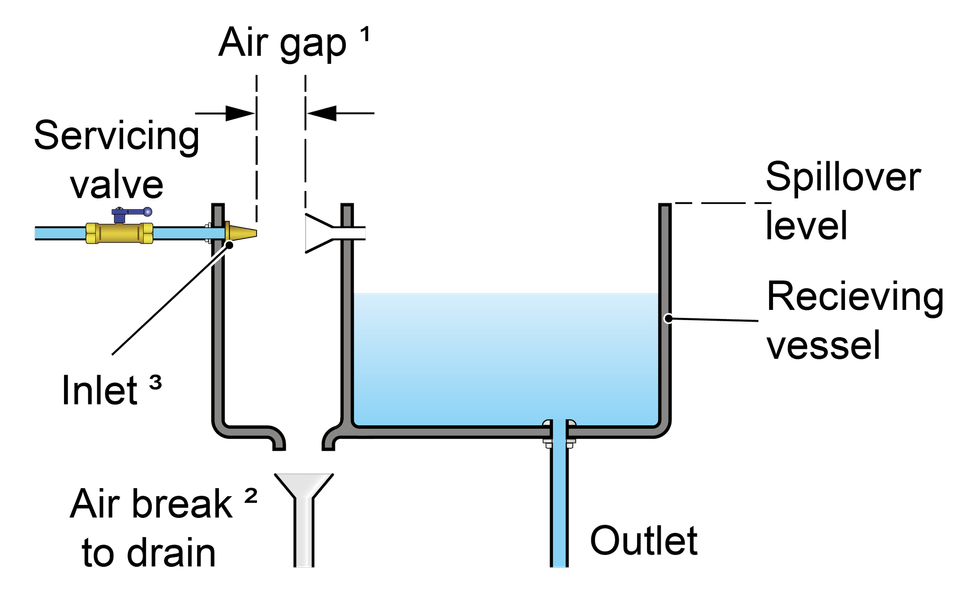
A summary of some of the key requirements applicable to a Type AD air gap is given below:
The air gap is an unobstructed and complete physical break between the terminal point of the injector and inlet orifice of the receiving vessel. Measured horizontally it must be no less than 20 mm or twice the internal diameter of the supply whichever is the greater.
The air break to drain must be open to atmosphere and capable of draining the maximum flow rate without submerging or coming into contact with the inlet.
The inlet must not come into contact with any splashing, drips or run off from the receiving vessel.
Type AD air gap installations should be inspected, and as necessary maintained every 6 months (BS EN 806: 5)
A Type AF air gap is a non-mechanical backflow prevention arrangement comprising of an inlet which discharges water into a cistern, vessel, fitting or appliance fitted (receiving vessel) fitted with an outlet and circular overflow.
A Type AF air gap is rated by the Regulators as suitable backflow protection against both back siphonage and back pressure for contamination risks no greater than fluid category 4.
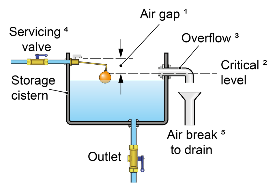
A summary of some of the key requirements applicable to a Type AF air gap is given below:
The air gap is an unobstructed and complete physical break measured downwards between the lowest point of discharge from the inlet and the critical water level. It must be no less than 20 mm or twice the internal diameter of the supply whichever is the greater.
The critical level is the fluid level in the receiving vessel under fault conditions i.e. when the outlet is closed but the inlet continues to discharge. It is measured at least 2 seconds after closing the water inlet
The overflow must be circular and of a minimum size throughout its length (four times in the inlet pipe cross sectional area). It must be capable of draining the maximum inflow of water under fault conditions i.e. when the outlet is closed but the inlet continues to discharge.
Submerged supply pipes are not permitted. If the supply pipe feeding the inlet or the inlet itself comes into contact with the contents of the receiving vessel, for example due to splashing or foaming, then the air gap is considered to be compromised and must be increased to the point no contact occurs.
Where they discharge to drain the overflow and warning pipe must be fitted with an air break to drain or equivalent prior to the drain connection.
Type AF air gap installations should be inspected, and as necessary maintained every 12 months (BS EN 806: 5)
A Type AG air gap is a non-mechanical backflow prevention arrangement comprising of an inlet which discharges water into a cistern, vessel, fitting or appliance fitted (receiving vessel) fitted with an outlet and minimum sized circular overflow.
A Type AG air gap is rated by the Regulators as suitable backflow protection against both back siphonage and back pressure for contamination risks no greater than fluid category 3.
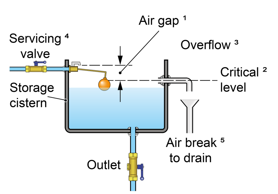
A summary of some of the key requirements applicable to a Type AG air gap is given below:
The air gap is an unobstructed and complete physical break measured downwards between the lowest point of discharge from the inlet and the critical water level. It must be no less than 20 mm or twice the internal diameter of the supply whichever is the greater.
The critical level is the fluid level in the receiving vessel under fault conditions i.e. when the outlet is closed but the inlet continues to discharge. It is measured at least 2 seconds after closing the water inlet
The overflow must be circular and a minimum of 19mm throughout its length. It must be capable of draining the maximum inflow of water under fault conditions i.e. when the outlet is closed but the inlet continues to discharge.
Supply pipes maybe submerged but adjustable or dismantlable joints on the are not permitted below the critical water level. If the inlet itself comes into contact with the contents of the receiving vessel, for example due to splashing or foaming, then the air gap is considered to be compromised and must be increased to the point no contact occurs.
Where they discharge to drain the overflow and warning pipe must be fitted with an air break to drain or equivalent prior to the drain connection.
Type AG air gap installations should be inspected, and as necessary maintained every 12 months (BS EN 806: 5)
A Type AUK1 air gap is a non-mechanical backflow prevention arrangement comprising of an interposed cistern fed via an inlet arrangement forming a Type AG air gap, and an outlet arrangement which discharges the contents by gravity into a separate receiving vessel. The receiving vessel (for example a WC pan or cistern) must be located a minimum distance below the interpose cistern. Depending on the outcome of an assessment by the local water undertaker can feed a single or multiple installations.
A Type AUK 1 air gap is rated by the Regulators as suitable backflow protection against back pressure risks no greater fluid category 3 and back siphonage risks up to and including fluid category 5.
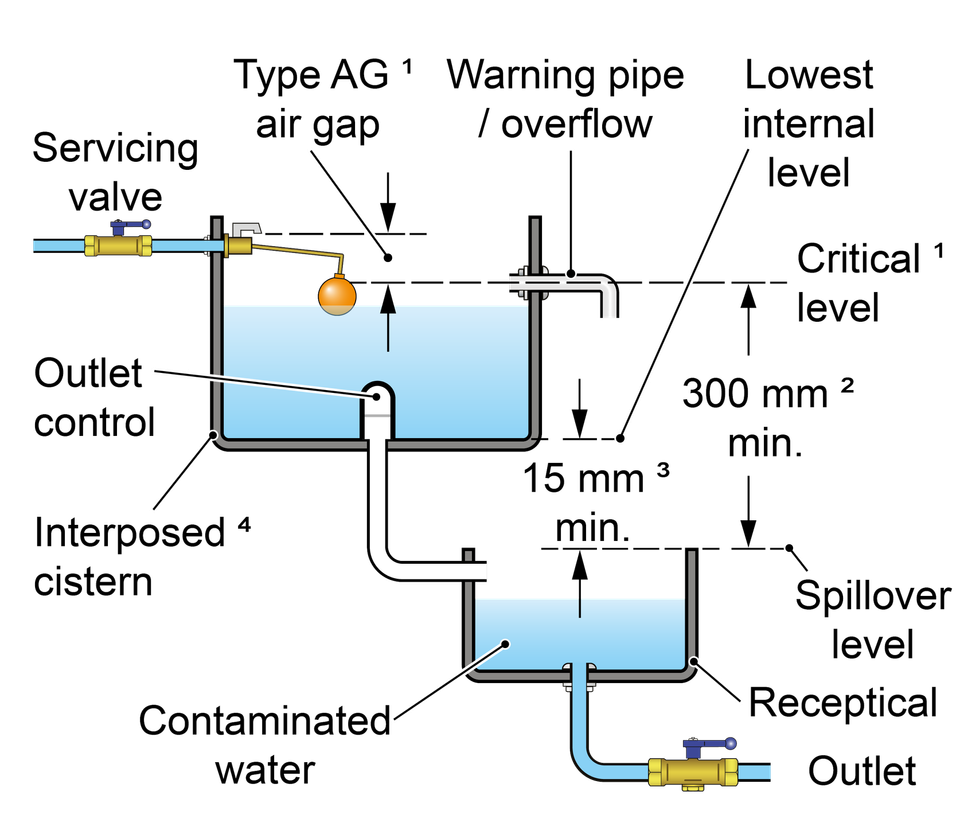
A summary of some but not all of the requirements applicable to a Type AUK1 air gap is given below:
The interposed cistern must conform to the requirements for a Type AG air gap.
The maximum fluid level in the receiving vessel must be a minimum of 300 mm below the spillover level of the interposed cistern and invert (lowest point of flow which may be different to the lowest point of discharge) of the warning pipe.
The maximum fluid level in the receiving vessel must be a minimum of 15 mm below the lowest internal water level of the interposed cistern.
The fluid in the interposed cistern must be categorised as no greater than fluid category 3.
As it includes a Type AG air gap, Type AUK 1 installations should be inspected, and as necessary maintained every 12 months (BS EN 806: 5)
Type AUK 2 tap gap is suitable for low risk installations (no greater than fluid category 3). It is a specific minimum distance between the lowest point of a tap spout, shower head or other fitting and the spillover level of the low risk receptable it supplies.
A Type AUK 2 tap gap is rated by the Regulators as suitable backflow protection against contamination risks no greater than fluid category 3 but for back siphonage only.
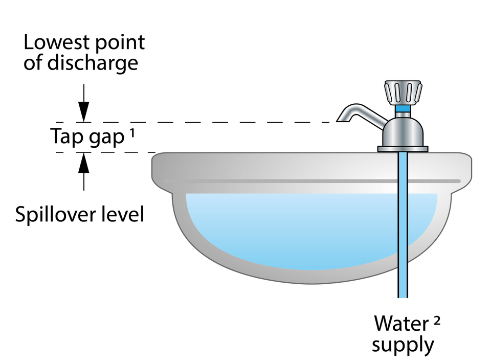
The requirements for a Type AUK2 tap gap are:
The tap gap is measured vertically from the lowest point of the outlet, which includes any aerator or flow straightener fitted, and the spillover level of whatever receptacle it supplies.
The gap required will vary depending upon the connection size of the tap or combination fitting as given below:
Connection size
Not exceeding ½“
Exceeding ½”but not exceeding ¾”
Exceeding ¾”
Tap gap
≥ 20 mm
≥ 25 mm
≥ 70 mm
A Type AUK 3 tap gap is suitable for high risk installations (fluid category 5 or lower). It is a specific minimum distance between the lowest point of a tap spout, shower head or other fitting and the spillover level of the high risk appliance or receptable it supplies.
A Type AUK 3 tap gap is rated by the Regulators as suitable backflow protection against the highest level of contamination, fluid category 5 but for back siphonage only.
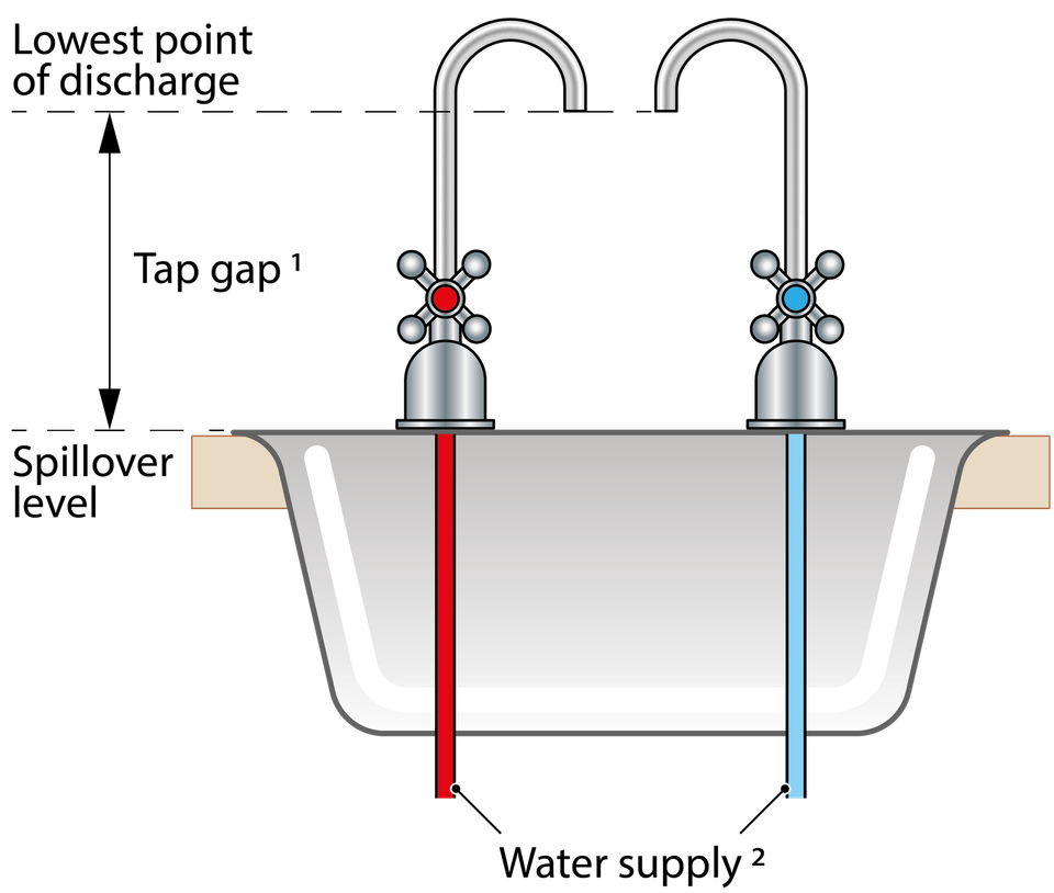
The requirements for a Type AUK3 tap gap are :
The tap gap is measured vertically from the lowest point of the outlet, which includes any aerator or flow straightener fitted, and the spillover level of whatever receptacle it supplies.
The gap required must be not less than 20 mm or twice the diameter of the inlet pipe supplying the installation whichever is the greater.
Where an AUK3 tap gap cannot be maintained, for example where the tap gap is compromised as a result of:-
the tap being lowered in any way;
adjustment to the spout which reduces the distance between the tap outlet and spillover level of the sink; or
the operation of a pull out hose attachment
An alternative form of fluid category 5 backflow protection is required.
A Type BA, more commonly known as a reduced pressure zone or RPZ valve, is a mechanical backflow protection device. It comprises of a combination of check and relief valves in different zones which perform specific functions to ensure there is no backflow should the downstream pressure become higher than the incoming supply or the valve malfunctions.
An RPZ valve is rated by the Regulators as suitable backflow protection against both back siphonage and back pressure for contamination risks no greater than fluid category 4 .
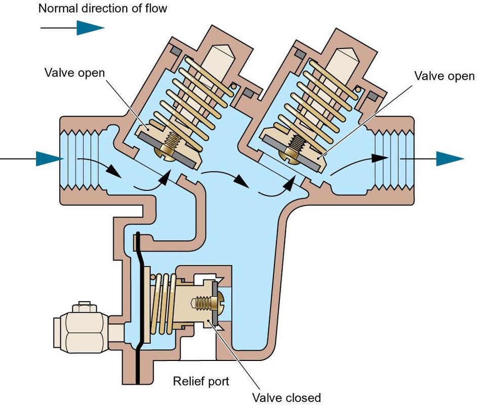
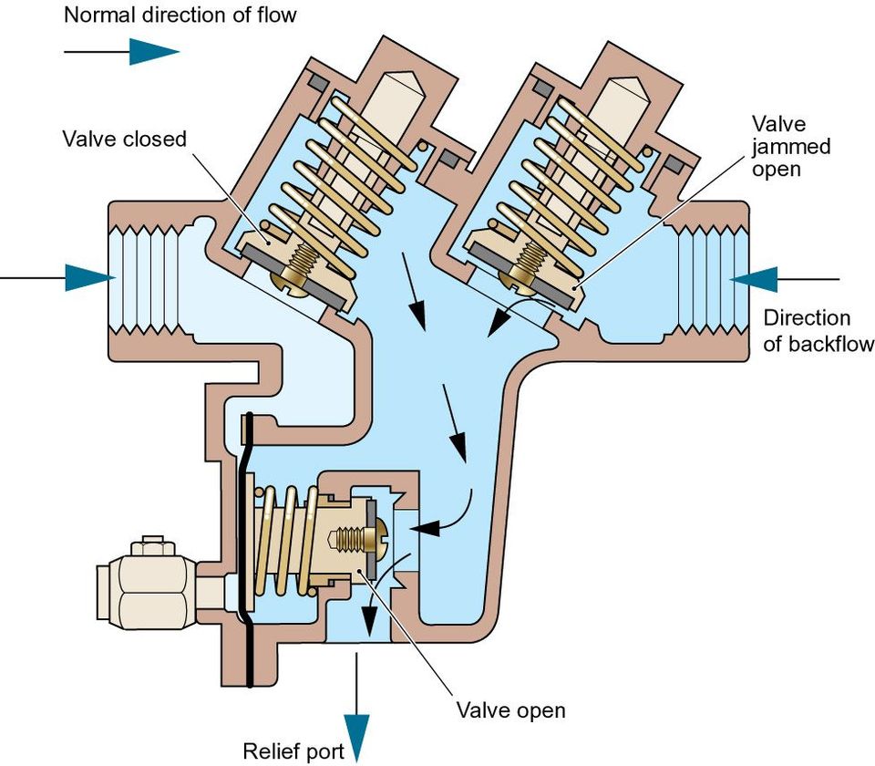
In addition to regular inspection RPZ valves are required to undergo routine testing to verify they are working correctly. For further information about this testing as well as specific installation requirements please refer to the RPZ AIM and FAQs. Please note testing intervals will be at the discretion of the local water undertaker but not less than annually.
A Type CA device is a mechanical backflow protection device. It comprises of a combination of check valves and a relief port. A disconnection is created as a result of the relief valve venting when the pressure differential across the check valves falls below 10% of the upstream pressure.
Type CA devices are rated by the Regulators as suitable backflow protection against both back siphonage and back pressure for contamination risks no greater than fluid category 3.

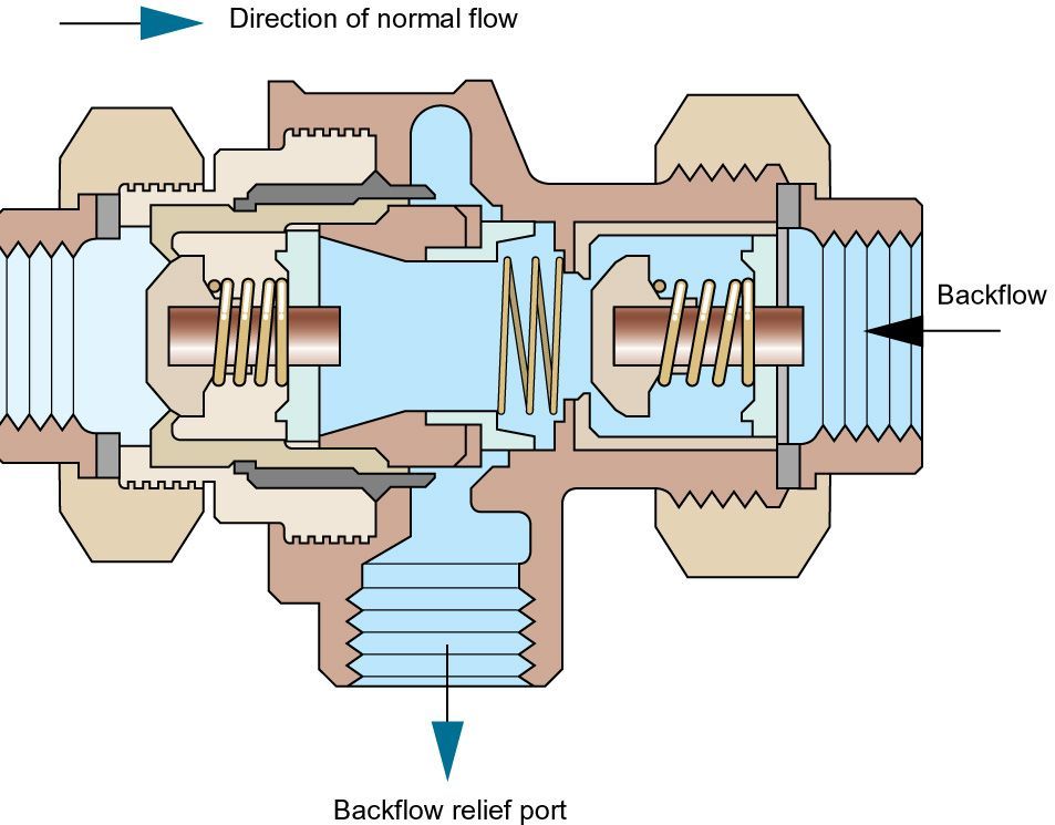
Type CA devices should be inspected every 6 months and as necessary maintained every 12 months (BS EN 806: 5)
A Type DB arrangement comprises of a pipe interrupter with a moving element (Type DB device) fitted not less than 300 mm above the spillover of any appliance or receiving vessel it supplies, discharging vertically downwards to an open outlet i.e. no method of flow control.
A Type DB arrangement is rated by the Regulators as suitable backflow protection against contamination risks no greater than fluid category 4 but for back siphonage only.
Type DB arrangements should be inspected and as necessary maintained every 12 months (BS EN 806: 5)
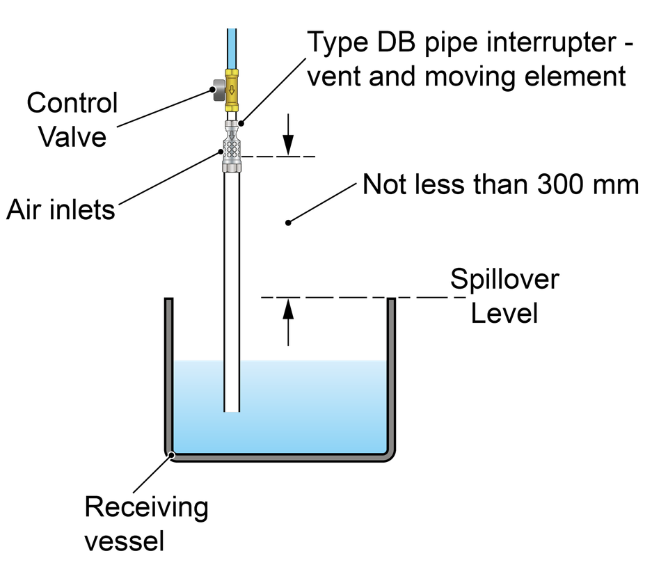
A DB device incorporates a moving element which closes the air inlets when the device is in use but opens to allow air if the upstream water pressure falls to atmospheric pressure.
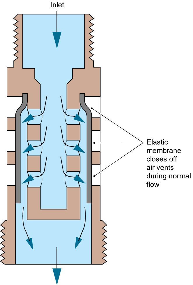
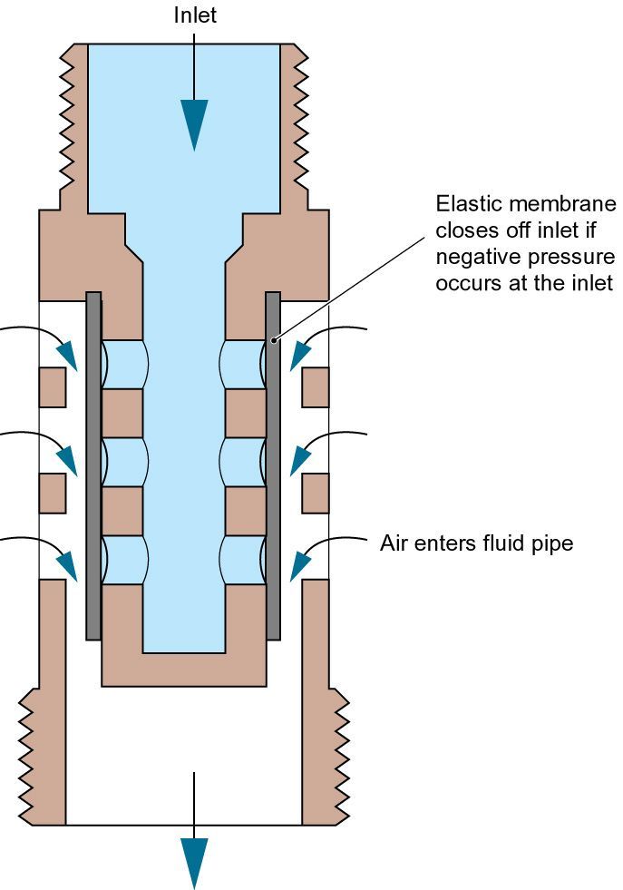
A Type DC arrangement comprises of a pipe interrupter with shrouded, permanently unrestricted air inlets (Type DC device) installed not less than 150 mm above the sparge outlet of a urinal or 300 mm (150 mm In Scotland) above the spillover of a WC pan or any other receiving vessel, discharging vertically downwards to an open outlet i.e. no method of flow control.
A Type DC arrangement is rated by the Regulators as suitable backflow protection against the highest level of contamination, fluid category 5 but for back siphonage only.
Type DC arrangement should be inspected, and as necessary maintained every 6 months (BS EN 806: 5)
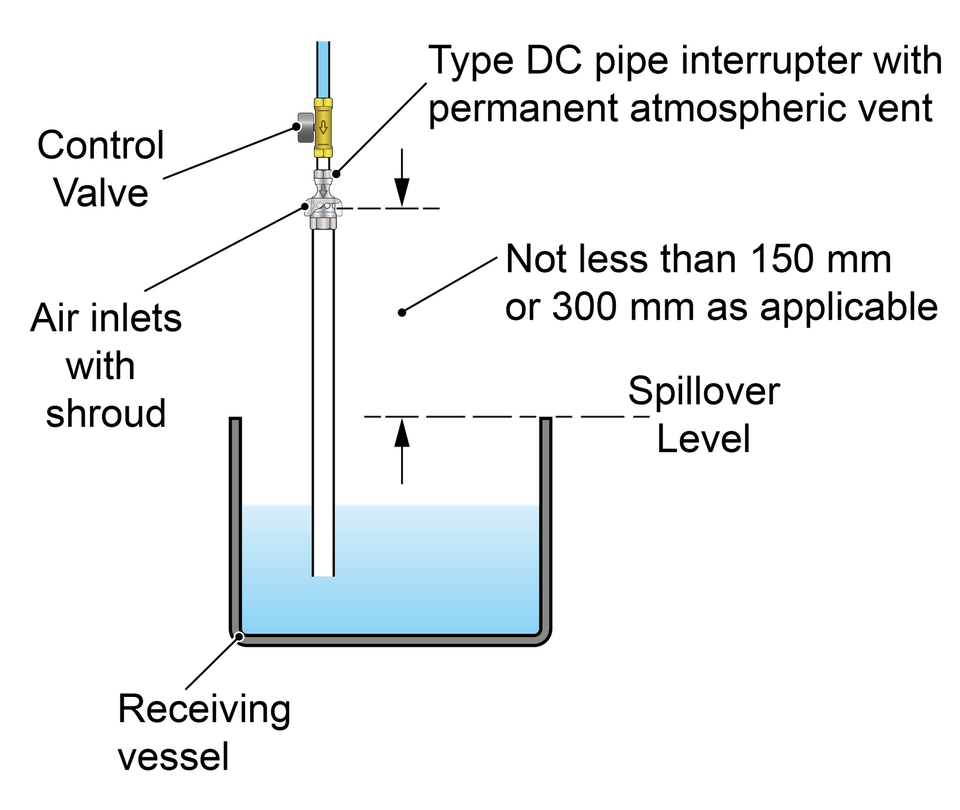
Type DC device
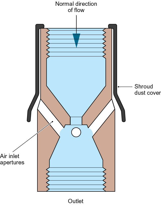

A single check valve is a mechanical backflow protection device. It permits water to flow from upstream to downstream but not in the reverse direction.
A single check valve is rated by the Regulators as suitable backflow protection against both back siphonage and back pressure for contamination risks no greater than fluid category 2.
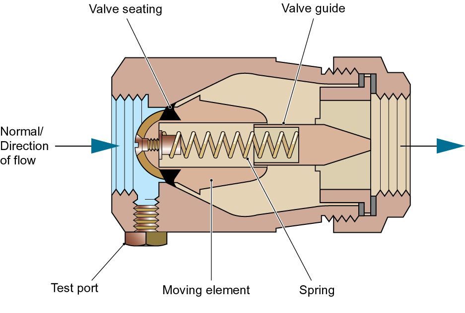
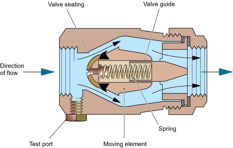
Single check valves should be inspected and maintained every 12 months: non-verifiable single check valves should be replaced every 10 years (BS EN 806: 5).
There are two ways to verify the backflow protection capabilities of single check valves, both rely on satisfying a specification including performance testing. These are:
Conformity with BS EN 13959, the British Standard for both single and double checks valves, this also includes provision for fittings incorporating these devices (or equivalent).
or
Conformity with all of the tests from the Regulators Specification for fittings applicable to devices intended to be used as a single or double check valve.
A double check valve is a mechanical backflow protection device. Comprising of two single check valves in series, a double check valve permits water to flow from upstream to downstream but not in the reverse direction.
A double check valve is rated by the Regulators as suitable backflow protection against both back siphonage and back pressure for contamination risks no greater than fluid category 3.
Double check valves should be inspected and maintained every 12 months: non-verifiable double check valves should be replaced every 10 years (BS EN 806: 5).
There are two ways to verify the backflow protection capabilities of a double check valve, both rely on satisfying a specification including performance testing. These are:
Conformity with BS EN 13959, the British Standard for both single and double checks valves, this also includes provision for fittings incorporating these devices (or equivalent).
or
Conformity with all of the tests from the Regulators Specification for fittings applicable to devices intended to be used as a single or double check valve.
Irrespective of what a device is called, for the purposes of the water fittings regulations, byelaws in Scotland, the important factor is whether it provides protection against backflow.
There are two ways to verify the backflow protection capabilities of a device, both rely on satisfying a specification including performance testing. These are:
Conformity with BS EN 13959, the British Standard for both single and double checks valves, this also includes provision for fittings incorporating these devices.
or
Conformity with all of the tests from the Regulators Specification for fittings applicable to devices intended to be used as a single or double check valve.
Both of these routes include endurance tests intended to demonstrate the device continues to operate correctly over its lifetime.
Example of a non-return valve
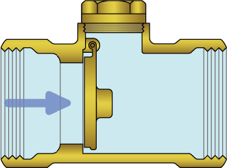
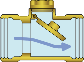
Example of a check valve
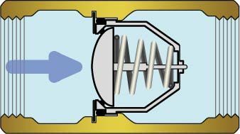
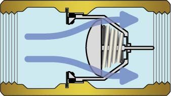
The terms ‘check valve’ and ‘non-return’ valve are both commonly used to describe a device which allows flow from upstream to downstream but not the reverse. Only valves, or fittings incorporating devices, which conform with one of the above specifications can claim to provide backflow protection.
Those meeting the requirements of a single check valve can be used for fluid category 2 backflow protection, whereas those satisfying the requirements for a double check valve can be used for up to fluid category 3 backflow protection.
Mechanical backflow prevention devices which, depending on the type of device, may be suitable for protection against backpressure or backsiphonage, or both, should be:
• Accessible for inspection, maintenance and replacement
• Installed in a workmanlike manner. For example, installed in accordance with any applicable requirements set out in:
Schedule 2 of the water fittings regulations, byelaws in Scotland
The Regulators Specification for backflow
The performance specification the device or arrangement confirms to
Water undertaker AIMs
BS EN 806 and/or BS 8558
Manufacturers instruction
Any conditions of product certification
Providing appropriate and adequate backflow protection against the highest level of risk downstream is installed, an installation not used to supply water for drinking, bathing, food preparation or cooking purposes is exempt from complying with schedule 2 paragraph 2(1).
Please note the backflow protection required needs to be assessed by the local water undertaker and other requirements of the water fittings regulations/byelaws continue to apply.
Schedule 2 paragraph 15 of the water fittings regulations in England, Wales and Northern Ireland, byelaws in Scotland require every plumbing system to incorporate protection against backflow, this is often referred to as point of use backflow protection.
To be accepted as providing adequate backflow protection the backflow device or arrangement installed typically should:
Firstly be approved by the Regulator or a relaxation to authorise its use granted
Secondly be rated equal to or higher than the highest contamination risk (fluid category) downstream for the type of backflow (back pressure or back siphonage) a system is likely to be exposed to.
Thirdly be of an appropriate quality and standard.
As some backflow prevention arrangements and devices have operational limitations you should always check with the local water undertaker to make sure they are suitable for the intended application.
Please note: if high risk contaminants are likely to be present in a plumbing system, because these represent a greater risk to health, in addition to any point of use protection the water undertaker can also require the installation of zone or wholesite backflow protection.
Regulators Specification: Non-mechanical backflow protection | |||
Type | Description | Suitability by fluid category | |
Back pressure | Back siphonage | ||
AA | Air gap with unrestricted discharge above spillover level | 5 | 5 |
AB | Air gap with weir overflow | 5 | 5 |
AC | Air gap with vented submerged inlet | 3 | 3 |
AD | Air gap with injector | 5 | 5 |
AF | Air gap with circular overflow | 4 | 4 |
AG | Air gap with minimum size circular overflow determined by measure or vacuum test | 3 | 3 |
AUK1 | Air gap with interposed cistern | 3 | 5 |
AUK2 | Air gaps for taps and combination fittings (tap gaps) discharging over domestic sanitary appliances, such as a washbasin, bidet, bath or shower tray shall not be less than the following: Size of tap or combination fitting . Not exceeding G ½ Exceeding G½ but not exceeding G ¾ Exceeding G ¾
Vertical distance bottom of tap outlet above spillover level of recieving appliance 20 mm 25 mm 70 mm
| X | 3 |
AUK3 | Air gaps for taps or combination fittings (tap gaps) discharging over any higher risk domestic sanitary appliances where a fluid category 4 or 5 is present, such as:
Shall be not less than 20 mm or twice the diameter of the inlet pipe to the fitting, whichever is the greater | X | 5 |
DC | Pipe interrupter with permanent atmospheric vent | X | 5 |
Notes:
| |||
Regulators Specification: Mechanical backflow protection | |||
Type | Description | Suitability by fluid category | |
Back pressure | Back siphonage | ||
BA | Verifiable backflow preventer with reduced pressure zone | 4 | 4 |
CA | Non-verifiable disconnector with difference between pressure zones not greater than 10% | 3 | 3 |
DA | Anti-vacuum valve (or vacuum breaker) | X | 3 |
DB | Pipe interrupter with atmospheric vent and moving element | X | 4 |
DUK1 | Anti-vacuum valve combined with a single check valve | 2 | 3 |
EA | Verifiable single check valve | 2 | 2 |
EB | Non-verifiable single check valve | 2 | 2 |
EC | Verifiable double check valve | 3 | 3 |
ED | Non-verifiable double check valve | 3 | 3 |
HA | Hose union backflow preventer. Only permitted for use on existing hose union taps in house installations | 2 | 3 |
HC | Divertor with automatic return (normally integral with some domestic appliance applications). | X | 3 |
HUK1 | Hose union tap which incorporates a double check valve. Only permitted for replacement of existing hose union taps in house installations | 3 | 3 |
LA | Pressurised air inlet valve | X | 2 |
LB | Pressurised air inlet valve combined with a check valve downstream | 2 | 3 |
Notes:
| |||
Point of use protection is backflow prevention provided at the point where water is being used. For example, at a tap, washing machine, WC or trough
Zone protection is a backflow prevention device or arrangement installed in addition to all existing point of use backflow prevention within a premises. Its purpose is to prevent backflow from one part of a plumbing system to another part of a plumbing system in the same property. For example, between different installations on one site. These are commonly found on farms, manufacturing sites and hospitals.
Whole site protection is a backflow prevention device or arrangement installed in addition to all other existing backflow prevention within a premises. Its purpose is to provide an additional level of protection to safeguard public water supplies to neighbouring properties.
Please note: the provision of zone and/or wholesite backflow prevention does not relax the requirement for any other required backflow prevention provision within premises.

Under schedule 2 paragraph 15(4) a water undertaker can require zone and/or wholesite protection to be installed.
The level of zone and whole-site backflow prevention required, and the type of backflow prevention device or arrangement to be used, is determined by the water undertaker. The provision of zone and/or whole-site backflow prevention does not relax the requirement for any other required backflow prevention provision within premises.
Appliances incorporating or supplied via a pump, such as power showers and washing machines, should not be fed from pipework which supplies high risk installations (fluid category risk 4 or 5) such as bidets adjacent to toilets
The booklet below provides details of when backflow protection arrangements and devices may be used.
Some but not all appliances incorporate backflow protection which satisfies UK requirements, conformity with BS EN 61770 does not. If the backflow protection built in is not adequate the appliance must be supplied via an independent appropriate form of backflow protection.
Please refer to the 'Whitegoods' information leaflet for further information.
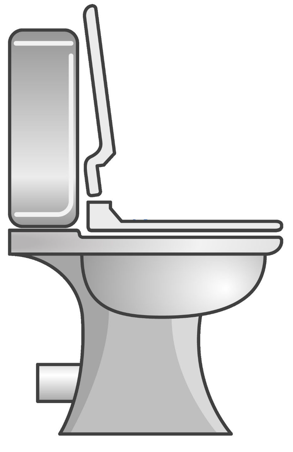
All water fittings in a bathroom must be supplied via an appropriate and adequate form of backflow protection, one which is rated either equal to or higher than the highest downstream contamination risk (fluid category) for the type of backflow (back pressure or back siphonage) it is likely to be exposed to.
A toilet is considered to be a fluid category 5 risk.
Typically, toilets have built in fluid category 5 protection such as a Type AUK1 backflow arrangement, but if not, they need to be supplied via a suitable backflow prevention arrangement offering fluid category 5 protection.
As some backflow prevention arrangements and devices have operational limitations you should always check with the local water undertaker to make sure they are suitable for the intended application.
For further information contact the local water undertaker.
All water fittings in a bathroom must be supplied via an appropriate and adequate form of backflow protection, one which is rated either equal to or higher than the highest downstream contamination risk (fluid category) for the type of backflow (back pressure or back siphonage) it is likely to be exposed to.
Urinals are considered to be a fluid category 5 risk.
1. A pressure flushing valve and Type DC device arrangement installed in accordance with the requirements of schedule 2 paragraph 25(c) in the relevant legislation in England, Wales, Scotland and Northern Ireland.
2. A flushing cistern which is supplied via an appropriate form of fluid category 5 backflow protection.
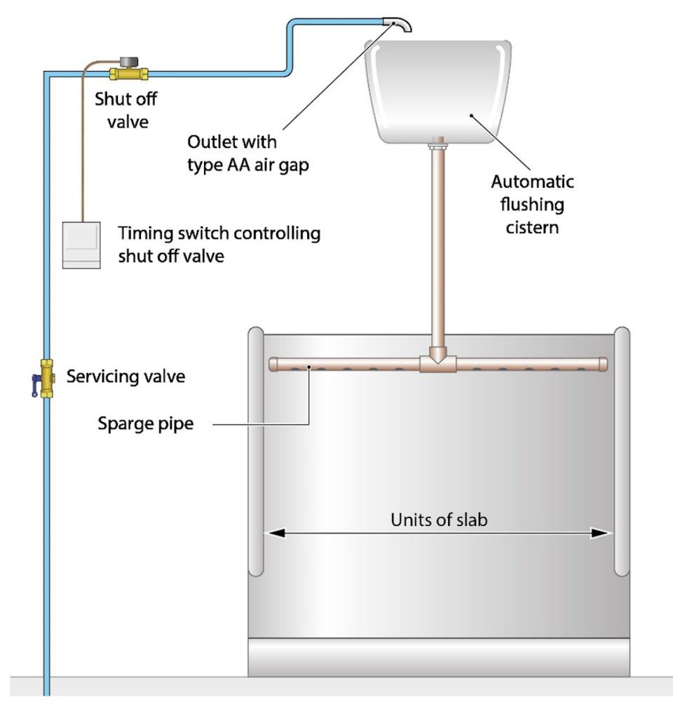
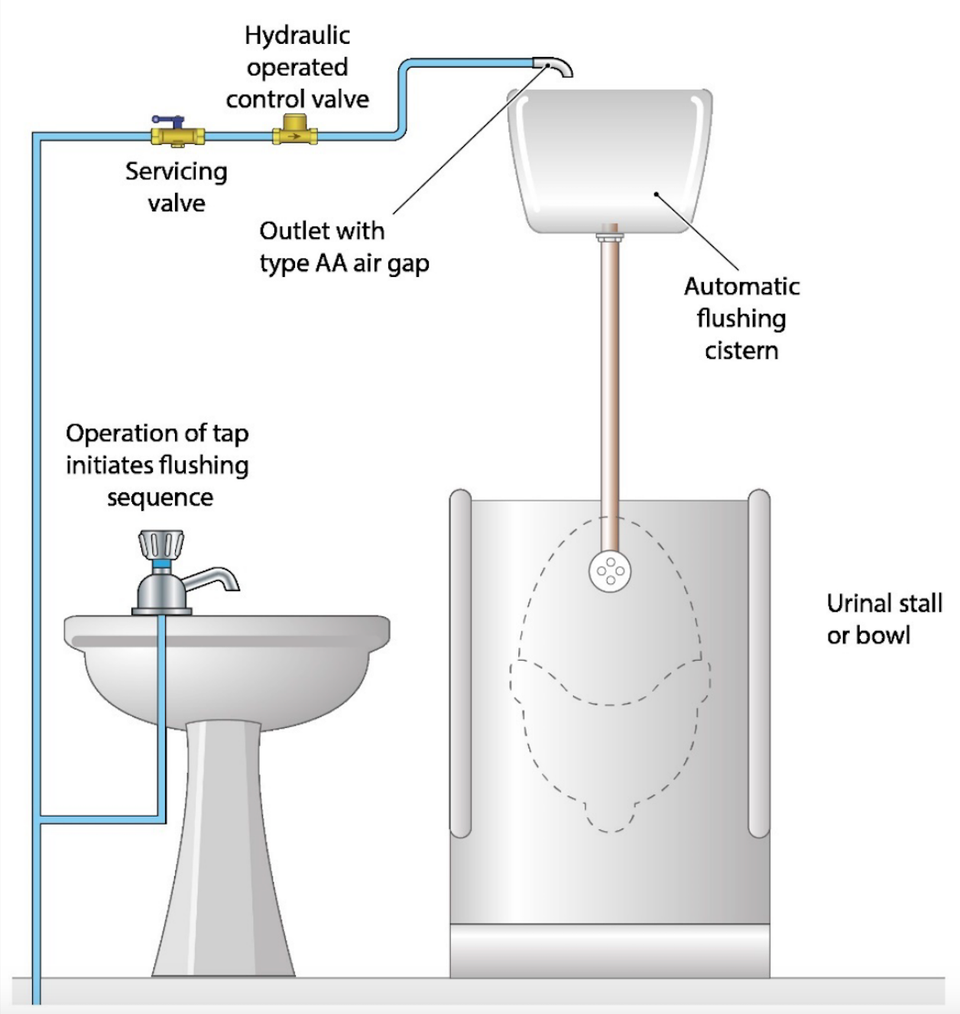
All water fittings in a bathroom must be supplied via an appropriate and adequate form of backflow protection, one which is rated either equal to or higher than the highest downstream contamination risk (fluid category) for the type of backflow (back pressure or back siphonage) it is likely to be exposed to.
Bidet showers adjacent to toilets are considered to be a fluid category 5 risk meaning both the cold water, and where appropriate hot water, must be supplied via a suitable form of fluid category 5 backflow prevention, for example via a break tank arrangement incorporating a Type AB air gap.
The installation of bidet showers is notifiable in Scotland and Northern Ireland and could be notifiable, for example as material change of use, in England and Wales. If notification is not required, for example because it is undertaken by an approved contractor, there remains a legal obligation for the premises owner or occupier to ensure the plumbing work is fully compliant with the water fittings regulations, byelaws in Scotland.
Providing the water is not to be used for drinking, cooking or any other forms of washing, the local water undertaker may be willing to consider permitting under conditional consent the use of the same dedicated fluid category 5 backflow protection and distribution arrangement to supply multiple bidet shower arrangements or another bidet, toilet or urinal in the same bathroom. Please note this will be dependent upon advanced notification of any proposed installation, including any to be completed by an approved contractor.
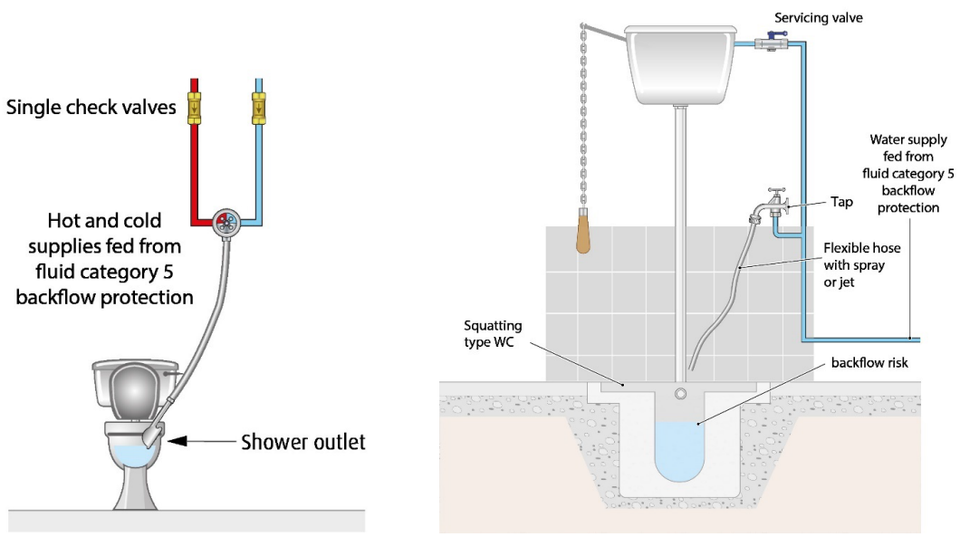
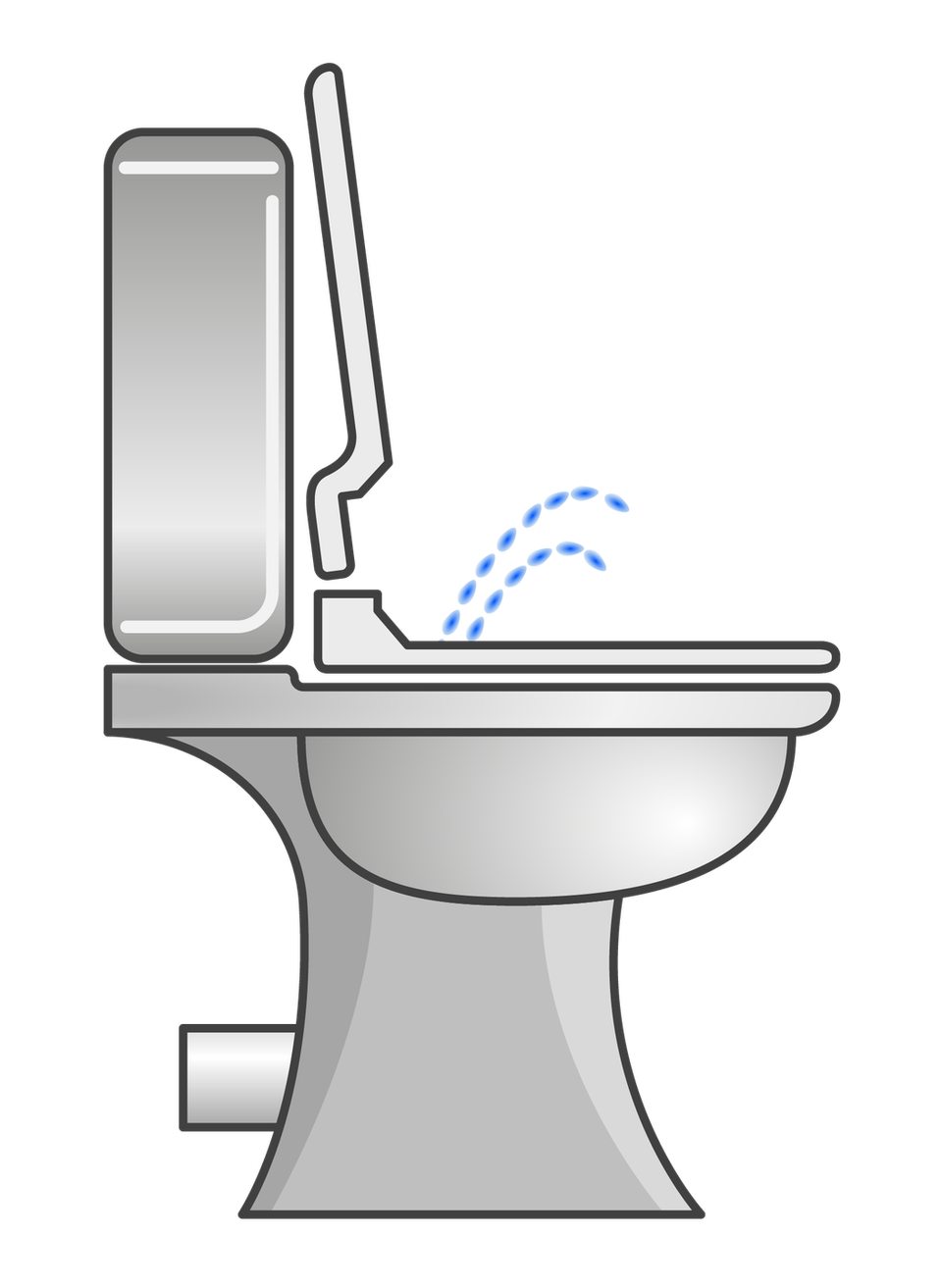
All water fittings in a bathroom must be supplied via an appropriate and adequate form of backflow protection, one which is rated either equal to or higher than the highest downstream contamination risk (fluid category) for the type of backflow (back pressure or back siphonage) it is likely to be exposed to.
A combined toilet and bidet is considered to be a fluid category 5 risk.
The installation of a combined toilet and bidet is notifiable in Scotland and Northern Ireland and could be notifiable in England and Wales as either a bidet or a material change of use. If notification is not required, for example because it is undertaken by an approved contractor, there remains a legal obligation for the premises owner or occupier to ensure the plumbing work is fully compliant with the water fittings regulations, byelaws in Scotland.
Some combined toilet and bidets incorporate backflow protection. Where this is the case, it is essential to confirm it meets all UK requirements, which is why it is so important to take advantage of the notification check offered by water undertakers.
If there is no acceptable built in backflow protection the installation must be supplied via a suitable form of fluid category 5 backflow prevention, for example via a break tank arrangement incorporating a Type AB air gap.
All water fittings in a bathroom must be supplied via an appropriate and adequate form of backflow protection, one which is rated either equal to or higher than the highest downstream contamination risk (fluid category) for the type of backflow (back pressure or back siphonage) it is likely to be exposed to.
Typically, bidets are considered to be a fluid category 5 risk, but some designs may be categorised as fluid category 3 in situations where the risk is considered to be lower, for example bidets supplied via taps above the spill over level in typical homes. It is however ultimately for the local water undertaker to determine what level of backflow protection is required.
The installation of a bidet with a hose handset or ascending spray (water outlet submerged i.e. below the bidet spill over level) is notifiable.
If notification is not required, for example because the work is undertaken by an approved contractor, there remains a legal obligation for the premises owner or occupier to ensure the plumbing work is fully compliant with the water fittings regulations, byelaws in Scotland.
Acceptable methods of backflow protection for bidets include:
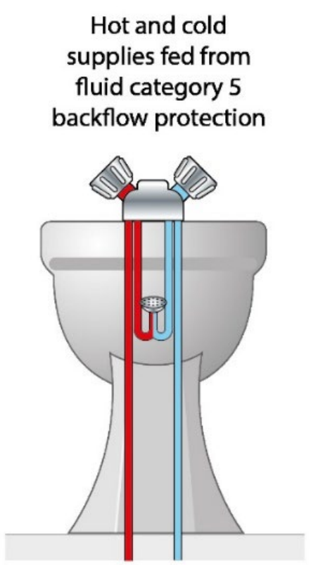
Both the cold, and where appropriate hot water, supply to a bidet must be supplied via a suitable fluid category 5 backflow prevention arrangement. For example, a break tank incorporating a Type AB air gap.
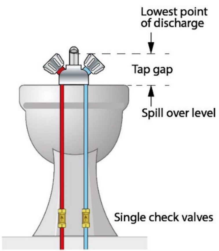
Providing an acceptable gap can be maintained between the lowest point of the tap outlet and spill over level of the bidet no additional backflow protection is required unless using a mixer tap which combines hot and cold water within the spout (single flow).
The gap required between the tap outlet and bidet spill over level will vary depending upon both the diameter of the pipework supplying the tap(s) and whether the bidet is fluid category 5 (Type AUK3 tap gap) or fluid category 3 (Type AUK2 tap gap).
If the bidet is supplied using single flow mixer tap (as opposed to a dual or bi-flow tap which has separate water paths to the end of the spout) in addition to maintaining the required tap gap single check valves will need to be installed on the pipework supplying the tap. This is to prevent cold water pressurising the hot water and hot water accessing the cold water mains supply under fault conditions.
If the outlet can become submerged, or the required tap gap cannot be maintained, the bidet must be supplied via a suitable form of fluid category 5 backflow protection.
Tap connection size | Minimum tap gap |
Up to and including 15 mm (½”) | 20 mm |
Larger than 15 mm (½”) but smaller than 20 mm (¾”) | 25 mm |
20 mm (¾”) or larger | 70 mm |
20 mm or twice the internal diameter of the tap connection whichever is the greater
For example: tap or shower size | minimum tap gap |
8 mm | 20 mm |
10 mm | 20 mm |
12 mm | 24 mm |
15 mm | 30 mm |
20 mm | 40 mm |
25 mm | 50 mm |
All water fittings in a bathroom must be supplied via an appropriate and adequate form of backflow protection, one which is rated either equal to or higher than the highest downstream contamination risk (fluid category) for the type of backflow (back pressure or back siphonage) it is likely to be exposed to.
Although ultimately it is for the local water undertaker to determine what level of backflow protection is required, showers in low risk environments, for example a typical home may be categorised as a fluid category 3 risk, whereas those installed in high risk situations, such as health care premises are a fluid category 5 risk.
If the installation of the shower is notifiable installation advice should be provided as part of the notification process.
If it is not notifiable there remains a legal obligation for the premises owner or occupier to ensure the plumbing work is fully compliant with the water fittings regulations, byelaws in Scotland.
Acceptable methods of backflow protection for showers include:
In all premises a shower arrangement (including those combined with fixed shower head outlets) with a hose handset capable of reaching into a toilet bowl or bidet (irrespective of the bidet design) is considered to be a fluid category 5 risk.
This means unless the shower hose can be permanently restrained or shortened to achieve a specific gap, known as a Type AUK3 tap gap, between the hose handset and spill over level of the toilet or bidet, all water supplies to the shower must be supplied via a suitable fluid category 5 backflow prevention arrangement. For example, a break tank arrangement incorporating a Type AB air gap.
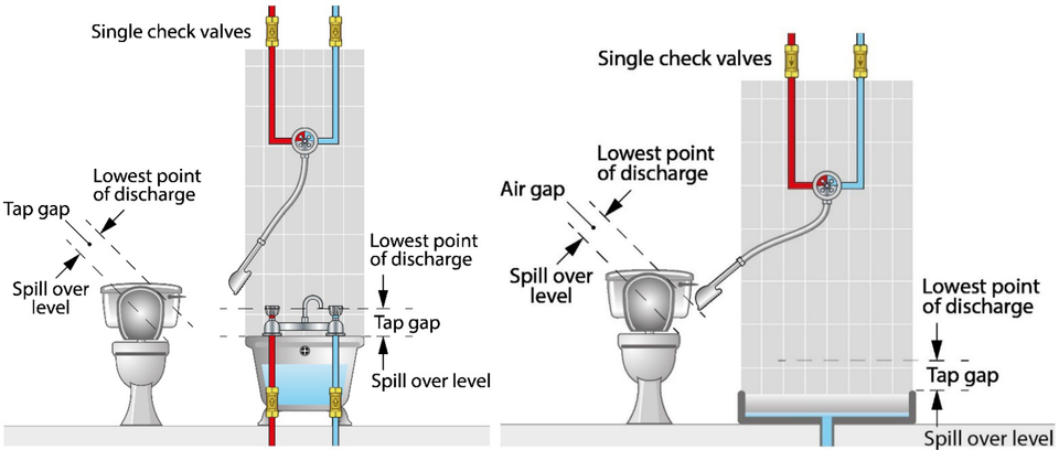
The hose handset being able to reach into a toilet bowl or bidet is not the only contamination risk of concern, preventing backflow from:
water from the bath or shower tray via the hose; and
either the cold or hot water supplies to the shower valve under fault conditions also needs to be addressed.
Typically, the risk of back siphonage of water in the bath or shower tray is tackled by ensuring the hose handset also maintains a suitable tap gap above the spill over level of the bath or shower tray. This gap will vary depending upon both the diameter of the pipework supplying the shower and whether the installation is fluid category 5 (Type AUK3 tap gap) or fluid category 3 (Type AUK2 tap gap).
If the shower handset cannot maintain the required tap gap then alternative backflow protection appropriate to the risk associated with the shower installation is needed.
The risk of cold water pressurising the hot water and hot water accessing the cold water mains supply under fault conditions is usually addressed by the installation of single check valves on the supplies to the shower valve. In the case of fluid category 3 shower installations if double check valves are fitted on the supply to the shower valve this would also address back siphonage via the hose where the required tap gap could not be maintained.
Fluid category 3: Type AUK2 tap gap
Tap or shower connection size | Minimum tap gap |
Up to and including 15 mm (½”) | 20 mm |
Larger than 15 mm (½”) but smaller than 20 mm (¾”) | 25 mm |
20 mm (¾”) or larger | 70 mm |
Fluid category 5 : Type AUK3 tap gap
20 mm or twice the internal diameter of the tap or shower connection whichever is the greater
For example: tap or shower size | minimum tap gap |
8 mm | 20 mm |
10 mm | 20 mm |
12 mm | 24 mm |
15 mm | 30 mm |
20 mm | 40 mm |
25 mm | 50 mm |
As with showers hoses it is important to address the risk of backflow of the bath or shower water via any fixed shower outlets as well as supplies to the shower valve.
The information relating to these two concerns given above also applies to these types of showers, but in the case of fixed shower heads the gap is measured between the lowest point of the shower head and spill over level of the bath or shower tray
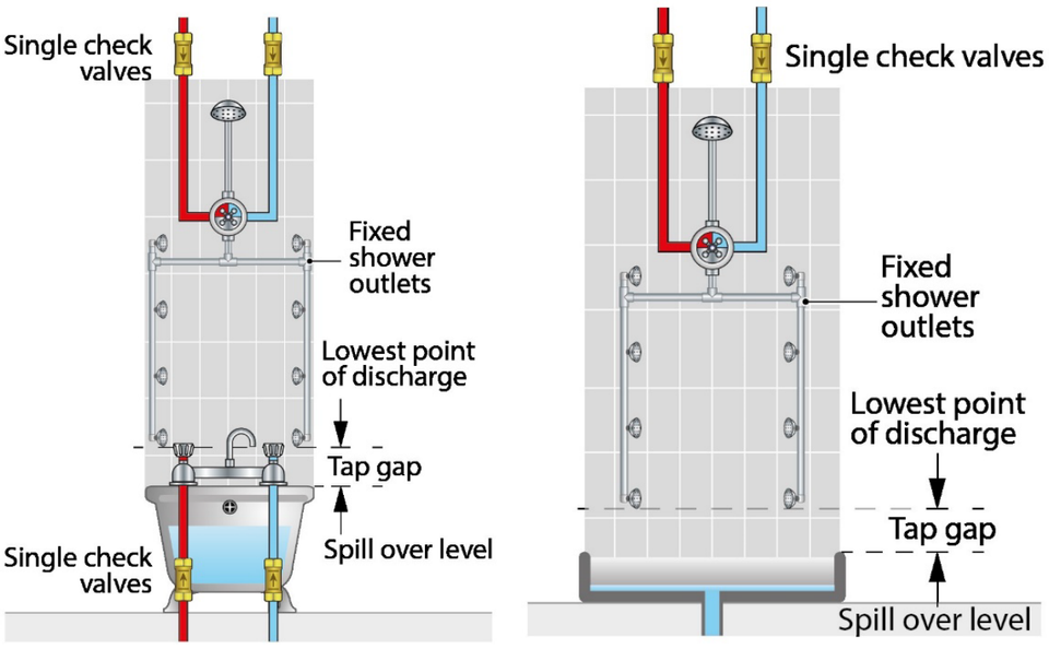
All water fittings in a bathroom must be supplied via an appropriate and adequate form of backflow protection, one which is rated either equal to or higher than the highest downstream contamination risk (fluid category) for the type of backflow (back pressure or back siphonage) it is likely to be exposed to.
The backflow risks associated with bath and basin taps will vary dependent upon their use (intended or otherwise) and the environment in which they are sited.
Although ultimately it is for the local water undertaker to determine what level of backflow protection is required, typically bath and basin taps used in domestic premises are categorised as a fluid category 3 risk, whereas those installed non-domestic premises can be a fluid category 5 risk.
There are a number of ways in which to prevent backflow via a tap, one of the most commonly used forms being a tap gap. A tap gap is a ‘gap’ between the lowest point of the tap outlet and spill over level of the bath, basin or bidet, the size of which varies depending upon the diameter of the pipe supplying the tap. If a tap gap cannot be maintained or the outlet is submerged, appropriate backflow protection is required. In domestic properties a double check valve is typically used.
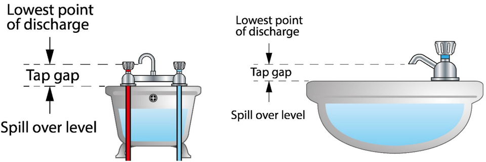
Fluid category 3: Type AUK2 tap gap
Tap connection size | Minimum tap gap |
Up to and including 15 mm (½”) | 20 mm |
Larger than 15 mm (½”) but smaller than 20 mm (¾”) | 25 mm |
20 mm (¾”) or larger | 70 mm |
Fluid category 5 : Type AUK3 tap gap
20 mm or twice the internal diameter of the tap connection whichever is the greater
For example: tap size | minimum tap gap |
8 mm | 20 mm |
10 mm | 20 mm |
12 mm | 24 mm |
15 mm | 30 mm |
20 mm | 40 mm |
25 mm | 50 mm |
Please note if tap is a single flow mixer tap (as opposed to a dual or bi-flow tap which has separate water paths to the end of the spout) in addition to maintaining the required tap gap single check valves will need to be installed on the pipework supplying the tap. This is to prevent cold water pressurising the hot water and hot water accessing the cold water mains supply under fault conditions.
If the installation is notifiable installation advice should be provided as part of the notification process.
If it is not notifiable there remains a legal obligation for the premises owner or occupier to ensure the plumbing work is fully compliant with the water fittings regulations, byelaws in Scotland.
All water fittings in a bathroom must be supplied via an appropriate and adequate form of backflow protection, one which is rated either equal to or higher than the highest downstream contamination risk (fluid category) for the type of backflow (back pressure or back siphonage) it is likely to be exposed to.
The backflow risks associated with a spa bath will vary dependent upon its design, use (intended or otherwise) and the environment in which it is sited. As they are potentially a fluid category 5 risk the local water undertaker should be contacted prior to installation.
All water fittings in a bathroom must be supplied via an appropriate and adequate form of backflow protection, one which is rated either equal to or higher than the highest downstream contamination risk (fluid category) for the type of backflow (back pressure or back siphonage) it is likely to be exposed to.
Bathing equipment in a nursing or care environment is considered to be a fluid category 5 risk. The supplies to all taps and showers outlets must be protected by a suitable form of fluid category 5 backflow protection. In practice this means being supplied from storage incorporating an adequate air gap (such as a Type AB air gap) or by maintaining a gap between a tap and shower outlet and spill over level of 20 mm or twice the diameter of the supply pipe (whichever is the greater) measured as shown below.
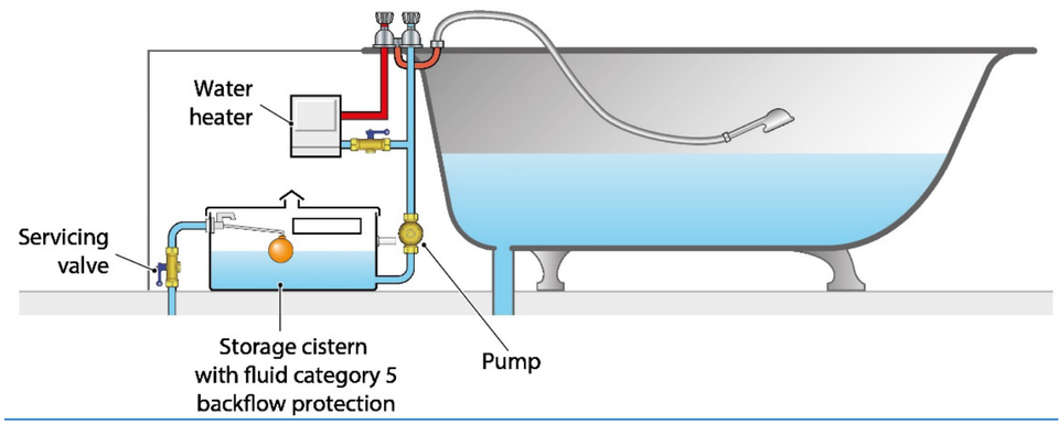
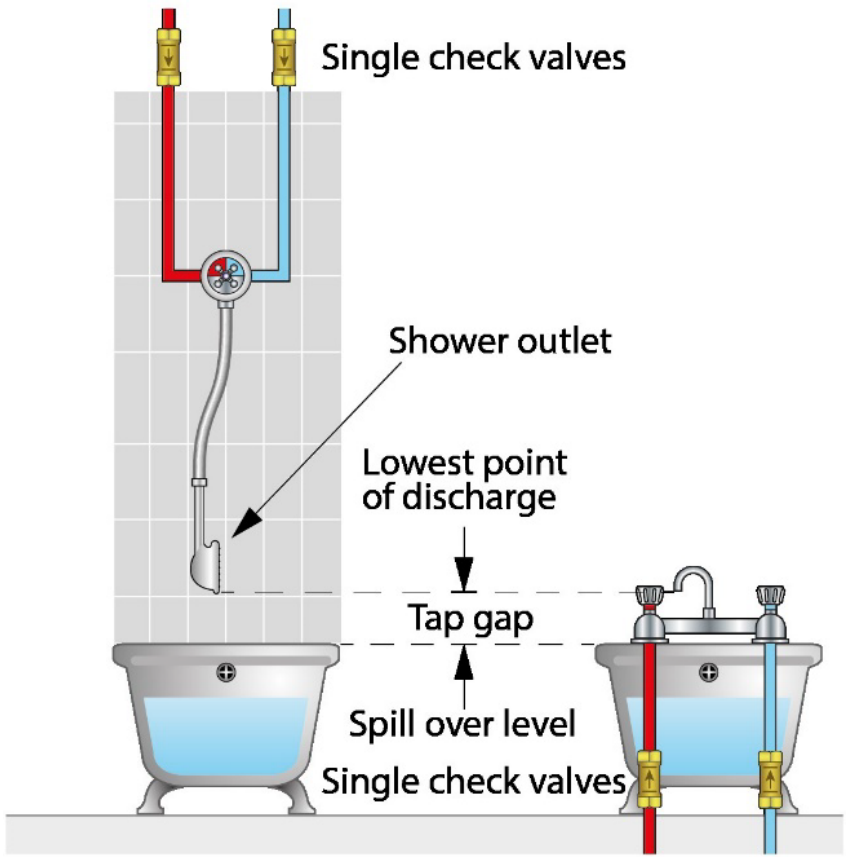
Fluid category 5 : Type AUK3 tap gap
20 mm or twice the internal diameter of the tap or shower connection whichever is the greater
For example: tap or shower size | minimum tap gap |
8 mm | 20 mm |
10 mm | 20 mm |
12 mm | 24 mm |
15 mm | 30 mm |
20 mm | 40 mm |
25 mm | 50 mm |
Please refer to the assisted bathing equipment leaflet for additional information.
In some cases, premises such as blocks of flats, terraced housing, caravans, holiday homes, office blocks, industrial units and student accommodation are supplied via a common supply or distribution pipe.
To prevent backflow between these separately occupied properties in addition to point of use protection the local water undertaker may require the installation of what is sometimes referred to as secondary protection. This is in effect a form of wholesite protection to protect the supplies to neighbouring properties as well as the main.
Although the level of protection required will be determined by the local water undertaker, typically a double check valve is used for this purpose.
Supplied direct from mains
Where fire suppression systems are supplied directly from a supply or distributing pipe conveying water to be used for domestic purposes (i.e. water used for drinking, bathing, cooking or washing.) backflow protection should be installed on the fire suppression system pipework as close as is reasonably practicable to the point of connection to the supply or distributing pipe.
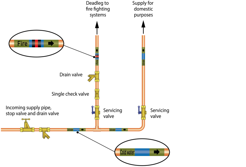
Fire suppression systems without additives are typically considered to a fluid category 2 risk. To be compliant a backflow protection rated to at least fluid category 2 must be installed on the branch supplying such systems as shown above.
Fire sprinkler systems using additives (e.g. rust inhibitors) are typically considered to be a fluid category 4 risk. To be compliant a backflow protection rated to at least fluid category 4 must be installed on the branch supplying such systems.
Supplied from dedicated storage
A storage cistern which is solely dedicated to supplying a fire suppression system is considered to be a fluid category 5 risk. To be compliant a backflow protection rated to at least fluid category 5 must be installed; typically a Type AB air gap is used for this purpose.
Furthermore, as the pipework supplying the storage cistern is considered to be a fluid category 2 risk, backflow protection rated to at least fluid category 2 must be installed as detailed above.
For further information about design and installation of fire suppression systems contact the local water undertaker.
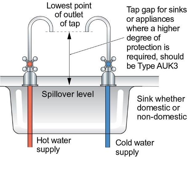
Providing a Type AUK3 tap gap is maintained a trigger-operated hose attachment used to pre-rinse crockery and cutlery in non-domestic premises only requires the installation of backflow protection rated at least fluid category 2 to ensure separation of the hot and cold supplies.
Fluid category 5 : Type AUK3 tap gap
20 mm or twice the internal diameter of the tap connection whichever is the greater
For example: tap size | minimum tap gap |
8 mm | 20 mm |
10 mm | 20 mm |
12 mm | 24 mm |
15 mm | 30 mm |
20 mm | 40 mm |
Please note
If the tap gap cannot be maintained for any reason, for example the spring retraction system is damaged, alternative means of providing fluid category 5 backflow protection will be required.
If there are any further questions, please contact the local water undertaker for advice.

Taps used in high risk installations, such as kitchen sinks, laboratories and medical facilities are considered to be a fluid category 5 risk. Backflow protection is usually provided in the form of an AUK3 tap gap i.e. an air gap of 20 mm or twice the internal diameter of the inlet pipe, whichever is the greater.
Fluid category 5 : Type AUK3 tap gap
20 mm or twice the internal diameter of the tap connection whichever is the greater
For example: tap size | minimum tap gap |
8 mm | 20 mm |
10 mm | 20 mm |
12 mm | 24 mm |
15 mm | 30 mm |
20 mm | 40 mm |
Where an AUK3 tap gap cannot be maintained, for example where the tap gap is compromised as a result of:-
the tap being lowered in any way;
adjustment to the spout which reduces the distance between the tap outlet and spillover level of the sink; or
the operation of a pull out hose attachment
An alternative form of fluid category 5 backflow protection is required.
If there are any further questions, please contact the local water undertaker for advice.
Laboratories and similar scientific facilities are considered to be a fluid category 5 risk, requiring fluid category 5 backflow protection.
In addition to point of use backflow protection, zone and wholesite protection may also be required.
Taps in laboratories
Point of use backflow protection can be provided in various ways including:
Type AUK3 tap gap:
A Type AUK3 tap gap may be accepted as point of use backflow protection. Unless it is considered the tap gap may be compromised, where this is the case an alternative form of backflow protection must be provided.
The tap gap is considered likely to be compromised where: -
The tap is designed to accommodate the attachment of a hose; or
The tap is intended to be adapted to accommodate the attachment of a hose: or
It is unlikely that the appropriate distance (tap gap) will be maintained between the tap outlet and spill-over level of the sink or other receptacle?
If laboratory taps can accommodate hoses, two separate aspects are considered:
Is it likely that a hose will be used to connect the tap to any laboratory equipment? If so, what are the risks associated with this equipment?
Does the discharge point of the hose (which includes hoses discharging from laboratory equipment supplied via a laboratory tap) fall below the spill-over level of the sink or receptacle?
Where a Type AUK3 tap gap cannot be maintained between the hose discharge point and the spill-over level of the sink/ receptacle alternative fluid category 5 backflow protection must be installed upstream of the tap.
Alternative backflow protection will be required where laboratory equipment, process or experiment is directly connected to the tap, even if a Type AUK3 tap gap can be maintained between the final discharge point and spillover level. The level of backflow protection will be determined by the level of risk associated with the equipment, chemicals/materials and/or processes involved.
Type DC arrangement:
A Type DC arrangement installed on a laboratory tap may be accepted as a means of point-of use fluid category 5 backflow protection providing:
The outlet, including the outlet of any hose attached: -
Remains unrestricted which would mean that it could not be attached to any apparatus that would create a back pressure
discharged at least 150mm below the air vents of the DC device, ruling out raising the hose outlet above this point
the spillover level of any receiving vessel is at least 150mm below the air vents
Only Type DC arrangements which satisfy these requirements will be acceptable. If these conditions are not maintained the water undertaker reserves the right to require the installation of alternative means of backflow protection.
Type DC arrangements are permitted to be used on outlets in fume cupboards which are handling chemicals. But are not suitable for outlets in biological safety cabinets or microbiological safety cabinets (biosafety cabinets) used with materials contaminated with pathogens which require a defined biosafety level. Water outlets in biosafety cabinets should be fed via a Type AA, AB or AD air gap.
For further information please refer to the advice booklet for schools, colleges and higher education establishments or contact the local water undertaker.
Where mains water and other water sources, such as rainwater, recycled water, river water and borehole supplies, combine it is essential to notify the relevant water undertaker to ensure adequate backflow protection arrangements are installed.
Alternative water supplies should never be directly connected to the mains drinking water. The only legal and safe way to combine mains and another source of water is to use an arrangement called a break tank which enables separation of supplies. Typically, this is done using a Type AA (as shown below) or Type AB air gap the key features being:
An unrestricted or weir spill over
The pipework supplying the mains water must be external to the tank
The mains water feed must discharge at a higher level than and maintain a minimum clearance (twice the internal diameter (2D) of the supply pipework or 20 mm whichever is the greater) from those supplying water from other sources
The water in the tank should not come into contact with the mains water inlet for example as a result of splashing.
This image below applies to any underground storage system:
Supplied directly from mains
Installed below-ground level, wholly or partially outside the thermal envelope.
Please refer to the Underground Storage Guidance booklet for further information.
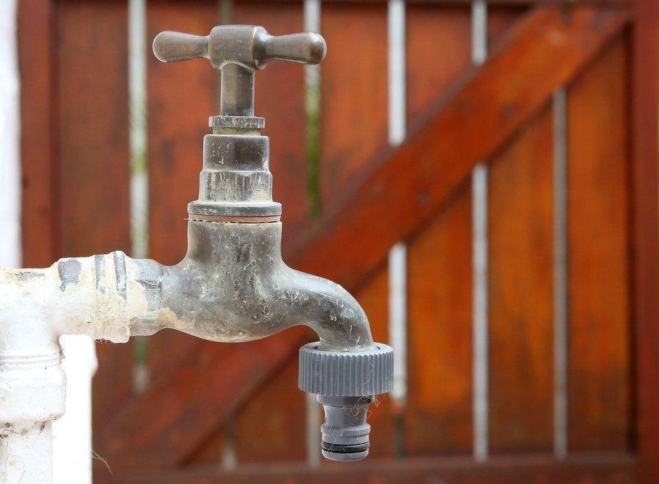 All hose union taps must be supplied via an appropriate and adequate form of backflow protection rated equal to or higher than the highest contamination risk (fluid category) downstream for the type of backflow (back pressure or back siphonage) it is likely to be exposed to.
As some backflow prevention arrangements and devices have operational limitations you should always check with the local water undertaker to make sure they are suitable for the intended application.
Where the local water undertaker requires it zone or wholesite backflow protection should be installed.
This image below is to be used in conjunction with the Camping sites, caravan holiday parks and residential park home estates booklet.
A hose union tap is a tap to which a hose can be connected. Hoses attached to hose union taps are considered to be a high contamination risk. This is because backflow via a hosepipe submerged in a bucket, trough, puddle, drain or pond is a very real possibility.
Conversely a tap to which a hose cannot be connected is called a bib tap. Providing that a suitable gap between the tap outlet and the spill over level of whatever it is discharging water into is maintained at all times these taps are typically considered to be a lower risk than a hose union tap.
To help prevent waste handheld hoses should be fitted with a control device, such as a trigger with a self-closing mechanism.
Please note: a control device is not a recognised form of backflow protection.
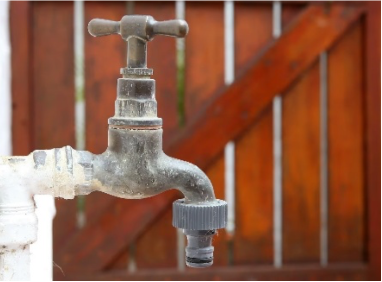
The backflow risks associated with hose union taps will vary dependent upon their use (intended or otherwise) and the environment in which they are sited. Ultimately it is for the local water undertaker to determine whether anything other than fluid category 5 backflow protection would be acceptable.
To protect public health the overriding concerns are whether there is a route through which backflow can occur and the likelihood of the tap being exposed to the fluids which pose a risk to health (highest applicable fluid category present)
In order that the correct level of backflow protection is identified and provided, the following factors will be considered:
1. The environment in which the hose tap is situated
In assessing the appropriate level of backflow protection required, account must be taken of:
The level of risk posed by potential contaminants. The highest level of fluid category to which the hose tap may or is likely to be exposed to will be the starting point in assessing the appropriate level of backflow protection required, regardless of whether a hose is or is not attached.
The intended use of the hose tap, and regardless of whether a hose is or is not attached.
2. Intended and/or potential uses
Where the intended use of the tap necessitates the attachment of a hose (whether a hose is attached or not) the potential reach of hose required to facilitate the intended use must be taken into account. Things which will be considered include:
Is a hose capable of being exposed to the highest fluid category identified in the vicinity?
Is there potential for the hose tap to be misused/vandalised, if so, does this alter the risk?
Is the use of a hose required? If a hose is not required to facilitate the intended use, the tap could be changed to a bib tap (tap without the provision to connect a hose).
3. The highest applicable fluid category
Domestic or non-domestic classifications are irrelevant in determining the highest applicable fluid category present. The backflow protection provided must be adequate and appropriate to the identified risk, as determined by the local water undertaker, taking account of the above considerations.
Below are examples of some high and low risk usage, please note the local water undertaker retains absolute discretion in determining the level of risk on a case by case and site specific basis.
Low risk activities
Providing the hose is:
Handheld (not left unattended)
Fitted with a flow control device
Disconnected from the hose union tap when not in use
Hoses used solely for watering a domestic garden or washing personal vehicles are typically categorised as a fluid category 3 risk which may be protected by the installation of a double check valve.
High risk activities
High risk activities include but are not limited to hose use:
Washing down farmyards, stables, kennels, catteries or other bird, fish or animal structures
Refilling and areas adjacent to ponds, swimming pools, spa baths or hot tubs
At abattoirs and mortuaries
At factories, distilleries, engineering, plating and chemical works
In catering facilities and public houses
In communal bin store areas
At allotments
Hose union taps used in these circumstances are classed as fluid category 5 risks unless an assessment by the local water undertaker determines otherwise. For further information and advice, and to ensure first time compliance, please contact your local water undertaker.
 The backflow risks associated with hose union taps will vary dependent upon their use (intended or otherwise) and the environment in which they are sited. Ultimately it is for the local water undertaker to determine whether fluid category 5 backflow protection is required.
Factors taken into account when assessing those supplying watering or irrigation systems included but are not limited to:
The use of chemical additives. For example, fertilisers, herbicides, and insecticides.
The irrigation system design. For example, pop-up sprinkler heads, seep hoses.
How the system is installed. For example, what parts of the system are below ground or permanently fixed above ground.
The size of the system and the environment in which it is installed.
The installation of an irrigation system must be notified, conditions are likely to apply To avoid the risk of cross connection with other supplies irrigation system pipework should be clearly marked in accordance with BS 1710.
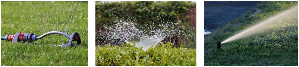
Hose union taps are typically categorised as a fluid category 3 or 5 risk. Below are some examples of backflow prevention which may be used where the hose union tap is categorised as either a fluid category 3 or 5 risk.
Example of fluid category 3 backflow protection arrangement
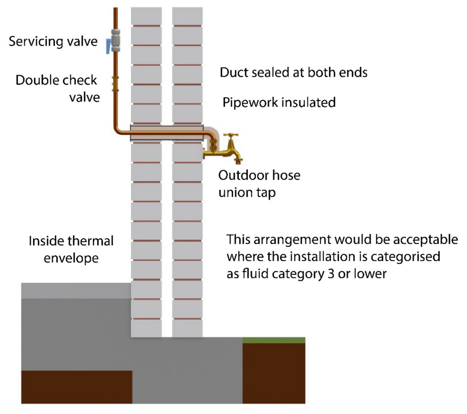
Example of fluid category 3 backflow protection arrangement
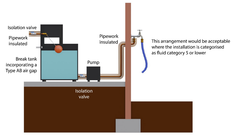
A Type AB air gap is a non-mechanical backflow prevention arrangement comprising of an inlet, receiving vessel and unrestricted weir overflow (rectangular or non-circular). To be considered as providing fluid category 5 backflow protection there must be an air gap of no less than 20 mm or twice the diameter of the supply whichever is the greatest, between the lowest point water discharges from the inlet and what is called the critical water level (also referred to as 'h'). The critical water level being the level reached in any part of the receiving vessel, including above the spill over level from the overflow, two seconds after the maximum water flow has ceased.
Please note:
If the supply pipe feeding the inlet or the inlet itself comes into contact with the contents of the receiving vessel, for example due to splashing or foaming, then the air gap is considered to be compromised and must be increased.
During fault conditions the water pathway to the overflow and discharge from the overflow itself must not be restricted. For example, there should be a sufficient gap between the overflow and any surface to accommodate full discharge unimpeded.
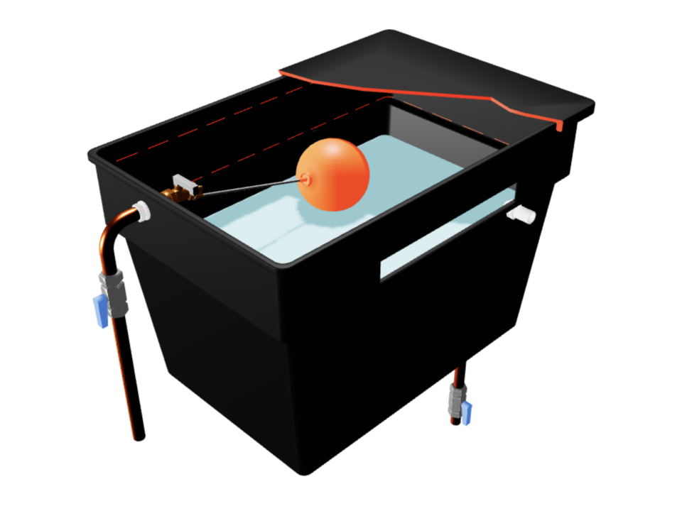
To be considered as providing fluid category 5 backflow protection, in addition to maintaining a suitable air gap, the water pathway to a Type AB air gap overflow, and discharge from the weir itself, must be unrestricted.
If the overflow is located close to another surface, such as a wall or other installation behind, in front or below the overflow, the gap between the discharge point and these surfaces must be sufficient to accommodate full discharge unimpeded. One way to demonstrate this is to ensure there is a clearance equivalent in shape and size to the weir overflow which is maintained to the air break to drain or floor level.
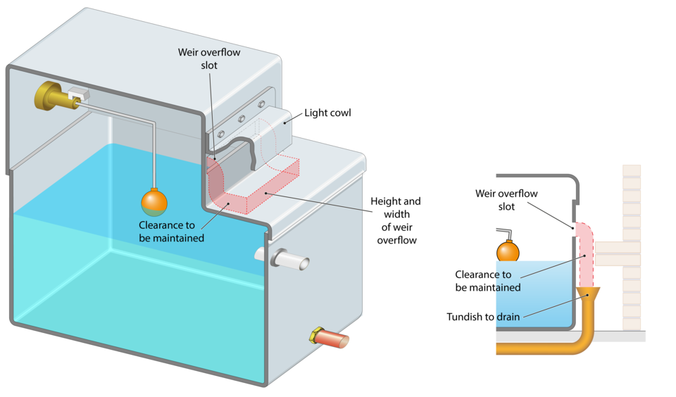
For the purposes of the water fittings regulations/byelaws approved contractor schemes are voluntary organisations for plumbers and plumbing contractors set up in accordance with regulation 1(2) of the water fittings regulations/byelaws. Approved contractors are either approved by a water undertaker or an organisation appointed by a regulator.
There is no mandatory requirement for plumbers to join a scheme.
There are currently five approved contractor schemes, some operate nationally and others in defined areas.
Some schemes restrict membership to qualified plumbers who can certify all types of plumbing work in any premises, whilst others offer sector schemes open to plumbing contractors who can certify a limited scope of plumbing work
Water Industry Approved | Approved by Regulator |
A Plus (Anglian Water) | |
Water Industry Approved Plumbers’ Scheme (WIAPS) operated on behalf of 17 water undertakers | Chartered Institute of Plumbing and Heating Engineering (CIPHE) |
Scottish and Northern Ireland Plumbing Employers’ Federation (SNIPEF) |
For the purposes of the water fittings regulations/byelaws an approved contractor, sometimes referred to as an approved plumber, is a member of one of the five approved contractor schemes.
Membership is voluntary rather than mandatory. Some schemes operate nationally and others in defined areas.
Only those with qualifications recognised by that scheme, as demonstrating competency to install in compliance with the water fittings regulations/byelaws, and suitable liability insurance can join a scheme.
Using an approved contractor means the plumbing work they undertake should be compliant with the water fittings regulations, byelaws in Scotland, but if not, the certificate of compliance, sometimes called a work completed certificate, they issue on completion can be used as a legal defence.
The water fittings regulations/byelaws include some notification exemptions for approved contractors, where this is the case, they do not have to provide advanced notification although it should be encouraged.
For further information about each, including how to join and the benefits of membership and using and approved contractor please contact the schemes or refer to the WaterSafe website.
Water Industry Approved | Approved by Regulator |
A Plus (Anglian Water) | |
Water Industry Approved Plumbers’ Scheme (WIAPS) operated on behalf of 17 water undertakers | Chartered Institute of Plumbing and Heating Engineering (CIPHE) |
Scottish and Northern Ireland Plumbing Employers’ Federation (SNIPEF) |
An approved contractor sector scheme is different to an approved contractor scheme in that its members are only recognised as being qualified to certify some plumbing work i.e. that defined in the sector scheme scope of accreditation.
Not all approved contractor schemes operate sector schemes.
One of the acceptance criteria for sector scheme membership is having a recognised qualification which demonstrates they are competent to undertake specific plumbing work in compliance with the water fittings regulations/byelaws.
There are a number of sector schemes including:
Groundworkers: these can work on supply pipes up to the internal stop valve
Catering Installers: these install commercial catering equipment
Point of use installers: these install cold water chillers connected directly to mains
RPZ valve testers: these undertake commissioning and compliance testing of RPZ valves
An approved contractor is a qualified plumber belonging to an approved contractor scheme. They can certify all types of plumbing work in any premises as being compliant with the water fittings regulations/byelaws.
A sector scheme member is not recognised as being a plumber but rather someone who does limited specific plumbing work. Sector scheme members can only certify the plumbing within the scope of that sector scheme i.e. some but not all types of plumbing work.
WaterSafe it is not an approved contractor scheme. It is a website which lists members of approved contractor schemes and a ‘brand name’ for promotion of approved contractors.
Its purpose is to provide a free online directory which the general public can use to find a competent qualified contractor in their area.

For the purpose of the water fittings regulations in England, Wales and Northern Ireland, byelaws in Scotland an approved contractor is a member of one of the following schemes.
Chartered Institute of Plumbing and Heating Engineering (CIPHE)
Scottish and Northern Ireland Plumbing Employers’ Federation (SNIPEF)
Providing:
Their scheme is recognised by the local water undertaker
The proposed work is not a material change of use
The scope of their membership covers the type of plumbing work undertaken
They comply with their scheme terms and conditions
An approved contractor installing the items highlighted in the list below, may not have to provide advanced notification before starting work. However, on completion they will be required to send a certificate of compliance for the work to the local water undertaker as well as issuing one to their client.
Please note: notification exemptions for those approved contractors who are members of sector schemes is typically restricted to the alteration or extension of plumbing systems. For further information contact the scheme
Please note: due to both differences in notification requirements across the UK and variation in individual approved contractor schemes terms and conditions it is important to check whether advanced notification is required.
For the purpose of the water fittings regulations in England, Wales and Northern Ireland, byelaws in Scotland an approved contractor is a member of one of the following schemes.
Chartered Institute of Plumbing and Heating Engineering (CIPHE)
Scottish and Northern Ireland Plumbing Employers’ Federation (SNIPEF)
Providing:
Their scheme is recognised by Scottish Water
The proposed work is not a material change of use
The scope of their membership covers the type of plumbing work undertaken
They comply with their scheme terms and conditions
An approved contractor installing the items highlighted in the list below, may not have to provide Scottish Water with advanced notification before starting work. However, on completion they will be required to send a certificate of compliance for the work to Scottish Water as well as issuing one to their client.
Any questions please contact the Scottish Water for advice.
Please note: notification exemptions for those approved contractors who are members of sector schemes is typically restricted to the alteration or extension of plumbing systems. For further information contact the scheme
Please note: due to both differences in notification requirements across the UK and variation in individual approved contractor schemes terms and conditions it is important to check whether advanced notification is required.
For the purpose of the water fittings regulations in England, Wales and Northern Ireland, byelaws in Scotland an approved contractor is a member of one of the following schemes.
Chartered Institute of Plumbing and Heating Engineering (CIPHE)
Scottish and Northern Ireland Plumbing Employers’ Federation (SNIPEF)
Providing:
Their scheme is recognised by Northern Ireland Water
The proposed work is not a material change of use
The scope of their membership covers the type of plumbing work undertaken
They comply with their scheme terms and conditions
An approved contractor installing the items highlighted in the list below, may not have to provide Northern Ireland Water with advanced notification before starting work. However, on completion they will be required to send a certificate of compliance for the work to Northern Ireland Water as well as issuing one to their client.
Any questions please contact the Northern Ireland Water for advice.
Please note: notification exemptions for those approved contractors who are members of sector schemes is typically restricted to the alteration or extension of plumbing systems. For further information contact the scheme
Please note: due to both differences in notification requirements across the UK and variation in individual approved contractor schemes terms and conditions it is important to check whether advanced notification is required.

Also known as a work completed certificate this is a certificate issued by an approved contractor or sector scheme member to the person who engaged them to carry out plumbing work.
The approved contractor or sector member must issue a certificate of compliance to their customer. If the work was notifiable under regulation 5 of the water fittings regulations/byelaws, they must also provide the local water undertaker with a copy.
By signing the certificate, the approved contractor is certifying the work has been undertaken by them, or in the case of some schemes under their direction and is compliant with the water fitting regulations/byelaws.
A certificate of compliance can be used as a legal defence by a customer if the certified work is later identified as being non-compliant.
Certificates issued by members of schemes approved by a regulator are acceptable nationally.
Certificates issued by a member of a water company scheme must be accepted for worked completed in that water company’s area of supply. Whilst water companies are not obliged to accept certificates issued by members outside their area of supply, the custom and practice is to do so providing:
Their scheme is recognised by the local water undertaker
The proposed work is not a material change of use
The scope of their membership covers the type of plumbing work undertaken
They comply with their scheme terms and conditions
A certificate of compliance is a legal protection for the recipient against prosecution where the certified work is deemed non-compliant. This does not prohibit water companies from taking other enforcement action.
You can search for approved contractors via the individual approved contractor schemes or WaterSafe.
WaterSafe is not an approved contractor scheme, it is a free website which the general public can use to search for a local approved contractor.
For further information please refer to WaterSafe.
You can confirm membership by using the WaterSafe search facility or contacting the scheme in question.
Water Industry Approved | Approved by Regulator |
A Plus (Anglian Water) | |
Water Industry Approved Plumbers’ Scheme (WIAPS) operated on behalf of 17 water undertakers | Chartered Institute of Plumbing and Heating Engineering (CIPHE) |
Scottish and Northern Ireland Plumbing Employers’ Federation (SNIPEF)
|
The WaterSafe website provides information about joining a scheme but ultimately you will need to contact the individual schemes to confirm whether you are eligible to join and apply.
The WaterSafe website provides information about recognised qualifications but ultimately you will need to contact the schemes to confirm whether you are eligible to join.
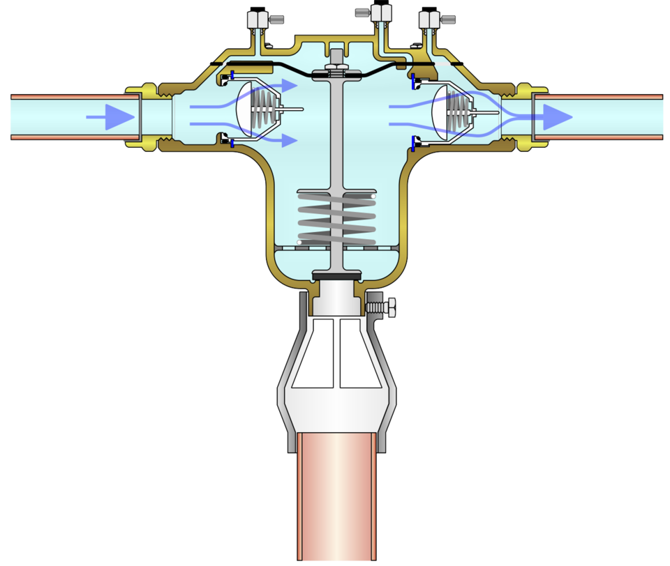 In addition to manufacturers installation instructions RPZ valves must be installed and tested in accordance with the RPZ AIM
Once installed an RPZ valve needs to be commission and compliance tested before it can be brought into service. The valve will also need to be compliance tested at regular intervals thereafter, as well as following relocation or repair.
To comply with the RPZ AIM commission and compliance testing should only be carried out by someone having an RPZ valve testing qualification recognised by the local water undertaker.
Details of what is required by water undertakers to be considered as evidence of competency to test an RPZ valve are provided in the RPZ AIM glossary.
Also known as a BA device, an RPZ valve is mechanical backflow prevention device capable of providing protection, against both back pressure and back siphonage, up to and including fluid category 4.
By means of a combination of check and relief valves an RPZ valve aims to ensure the water downstream is at a lower pressure than the incoming supply.
The installation, including relocation, of RPZ valves must be notified to the local water
undertaker. RPZ valves must be installed and tested in accordance with the Water Industry RPZ Approved Installation Method (AIM ).
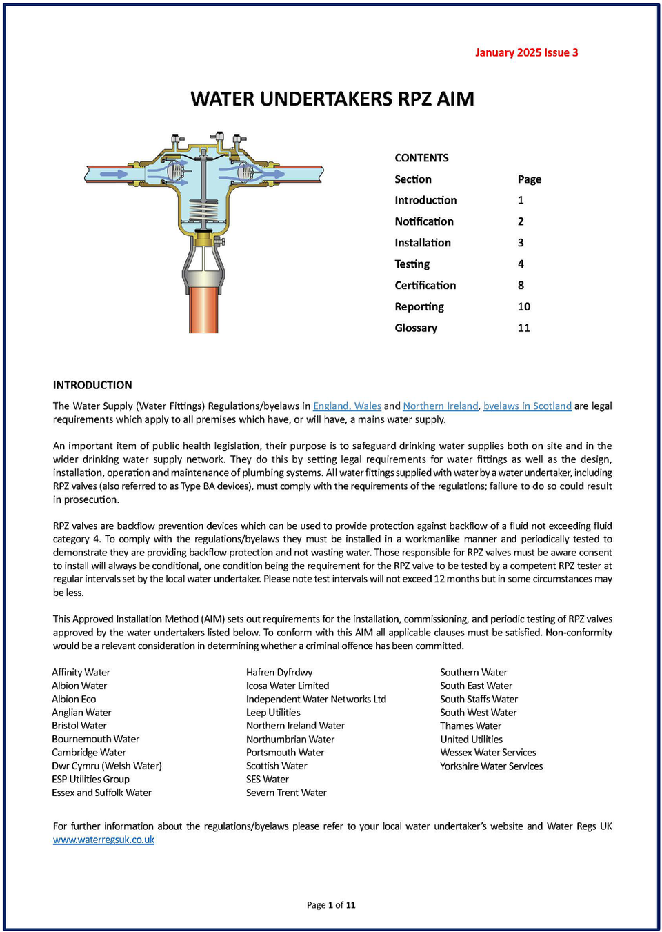
An installation method (AIM) is a procedure approved by Water undertakers.
The current version of the RPZ AIM, came into force on 1st January 2025. It provides procedures for both installing and testing of RPZ valves.
It is approved the water undertakers in England, Scotland, Wales and Northern Ireland listed on page 2.
A copy of the current version of the AIM, can be found on the Water Regs UK website or click here
Please note: the AIM requires test equipment to meet a minimum specification.
RPZ valves, or BA devices, are a recognised form of backflow prevention offering protection against back pressure and back siphonage up to and including fluid category 4.
If a plumbing system in your premises has been categorised as fluid category 4 or less by your water undertaker, then an RPZ valve may be an appropriate form of point of use backflow protection. An information leaflet highlighting things those responsible for plumbing systems should be aware of if thinking about installing or already have RPZ valves installed can be found here.
An RPZ valve may also be suitable for wholesite backflow protection. For further information consult the local water undertaker.
Please note:
Only RPZ valves installed and tested in accordance with the RPZ AIM will be considered as providing backflow protection.
To show they are functioning satisfactorily all RPZ valves are required to be regularly tested by a competent RPZ tester. Test intervals are set by the local water undertaker. Whilst test intervals may vary, they will be at least annually.
The water fittings regulations in England, Wales and Northern Ireland, byelaws in Scotland, categorise the risk to health posed by potential contaminates by fluid categories. There are five in total, the lowest being 1 (wholesome water) and the highest 5 (a serious health hazard).
Fluid category 4 is something which poses a significant health hazard. Examples include carcinogens, pesticides and environmental organisms of potential health significance.
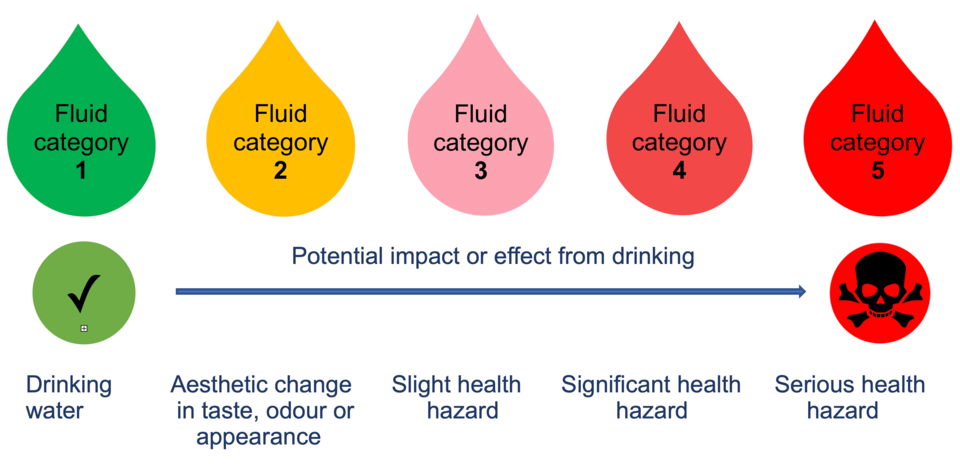
If a system in your premises has been categorised as fluid category 4 or less by your water undertaker, then an RPZ valve may be an appropriate form of point of use backflow protection. For further information consult the local water undertaker.
Please note:
Only RPZ valves installed and tested in accordance with the RPZ AIM will be considered as providing backflow protection.
To show they are functioning satisfactorily all RPZ valves are required to be regularly tested by a competent RPZ tester. Test intervals are set by the local water undertaker. Whilst test intervals may vary, they will be at least annually.
If there is an RPZ valve installed at a premises you are responsible for, the things you need to do include:
Familiarise yourself with the RPZ AIM
Make sure the local water undertaker has been notified the valve exists and has granted consent and familiarise yourself with the conditions of consent
Confirm the valve has been installed and tested in accordance with the AIM and the conditions of consent issued by the local water undertaker
Ensure the valve is ‘in test’ – it has been tested within the timeframe specified in the condition of consent, by a competent tester using equipment which meets the required minimum specification and satisfies all the appropriate clauses of the RPZ AIM.
Make certain a copy of the test report has been sent to the local water undertaker within the required timescales
As part of your maintenance procedures consider maintaining a technical file
Notify the local water undertaker if you plan on any alterations to the plumbing on site including removing, relocating or replacing the RPZ valve
An information leaflet highlighting things those responsible for plumbing systems should be aware of if thinking about installing or already have RPZ valves installed can be found here.
Potential users of RPZ valves must be aware that water undertaker’s consent will always be conditional upon installation, commissioning and compliance testing requirements.
If you are thinking about an RPZ valve installed at premises you are responsible for, things you need to do include:
Speaking with the local water undertakers to find out whether you need an RPZ valve and if so where, and the valve, you are planning to install is suitable
Notify the local water undertaker
Familiarise yourself with the RPZ AIM,
Consider whether an RPZ valve is right for you – consent to install will always be conditional on ongoing testing requirements.
An information leaflet highlighting things those responsible for plumbing systems should be aware of if thinking about installing or already have RPZ valves installed can be found here.
It means there is an RPZ valve on-site which needs to be compliance tested by a competent RPZ tester no later than the test due date in order to comply with the conditions of consent which permitted its installation.
One way to identify a competent RPZ tester is to search using the WaterSafe website.
It is important to act as failure to comply with the requirements specified as a condition of consent may result in the water undertaker taking enforcement action which may include temporarily disconnecting the water supply to the premises and requiring the removal of the RPZ valve. Reconnection shall only be with the agreement of the water undertaker
Contact the local water undertaker for further information.
If you cannot find the answer you are looking for here, please refer to the local water undertaker for further advice. Contact details can be found on the contact’s page .
There are no legal restrictions on who can install an RPZ valve. But anyone installing one should be competent to do so and the valve installed and tested in accordance with all the condition of consent which apply.
Water undertakers recommend a competent installer, such as an approved contractor, is engaged to undertake this work.
If there are any questions about the conditions of consent, contact the local water undertaker for further information.
The installation requirements for RPZ valves will be set out in the conditions of consent.
As a minimum they will include compliance with the installation requirements set out in section 4 of the RPZ AIM
There are no legal restrictions on who can remove an RPZ valve. But anyone removing one should be competent to do so, for example an approved contractor, and the alteration be in compliance with the requirements of the water fittings regulations in England, Wales and Northern Ireland, byelaws in Scotland.
The local water undertaker is also required to be notified
Please refer to the local water undertaker's website for further information.
Providing water undertakers with advanced notice of most types of proposed plumbing work is a legal obligation under the water fittings regulations in England, Wales and Northern Ireland, byelaws in Scotland. If a non-domestic premises has a mains water supply, the plumbing work that can be undertaken on-site without notification is very limited and maybe even further restricted by the conditions of supply.
It is a requirement of the RPZ AIM that prior notice be given for the installation of all RPZ valves. Details of the proposed work/installation shall be sent to the relevant water undertaker no less than 10 working days before work is due to start. Installing or using RPZ valves without the required consent could result in enforcement action being taken by the water undertaker.
Potential users of RPZ valves should be aware a water undertaker’s consent will always be conditional upon installation, commissioning and compliance testing requirements. An information leaflet highlighting things those responsible for plumbing systems should be aware of if thinking about installing or already have RPZ valves installed can be found in the Things you need to know about RPZ valves information leaflet.
Details of the proposed work/installation shall be sent to the relevant water undertaker no less than 10 working days before work is due to start. Installing or using RPZ valves without the required consent could result in enforcement action being taken by the water undertaker.
An information leaflet highlighting things those responsible for plumbing systems should be aware of if thinking about installing or already have RPZ valves installed can be found in the Things you need to know about RPZ valves information leaflet.
Please note that failure to provide the minimum level of information required may delay consent. Contact the local water undertaker for further information.
Identify the local water undertaker using the company contacts page . Complete their notification form and submit to the address provided.
Water undertakers may withhold or grant consent. Consent for the installation of a RPZ valve will always be subject to conditions. These may include specific requirements in addition to the general requirements set out in the RPZ AIM, all conditions set shall be complied with.
Please note that failure to provide the minimum level of information required may delay consent. Please contact the local water undertaker for further information.
Approved contractors are exempt from notifying certain plumbing work. However, this exemption does not include the construction of new premises or the installation of a new high risk system (fluid category 4 or 5).
In the case of existing high risk installations, although some approved contractor schemes do not require their members to notify the installation of an RPZ valve the majority are required to do so as part of their scheme terms and conditions. Installation of an RPZ valve in Scotland and Northern Ireland is always notifiable.
Those not required to notify are nevertheless encouraged to do so. This is to assist their customers as they, not the installer, will be responsible for the RPZ once installed and have to comply with the RPZ AIM
In order for the valve to be consider as compliant or ‘in test’ an on-site commissioning and compliance test report have to be submitted to the local water undertaker and test intervals for subsequent testing confirmed by the water undertaker.
No, therefore it is important to use a water undertaker’s forms especially when submitting information electronically
Details of the minimum information needed by a water undertaker, for consent to install a RPZ valve, are set out in regulation 5 they are also provided appendix 2 of the RPZ AIM. Please note that failure to provide the minimum level of information required may delay consent.
Contact the local water undertaker for further information.
Changes to an existing RPZ valve which are required to be notified will be listed in the condition of consent letter issued by the local water undertaker.
These could include, but are not limited to:
Changes in location
Substitution of a RPZ valve
Removal of an RPZ valve
Any other changes to plumbing installations.
Where the water fittings regulations in England, Wales and Northern Ireland, byelaws in Scotland apply advanced notice is required for most types of proposed plumbing work.
Water undertakers have 10 working days to respond. They can withhold or grant consent, which is their official approval for the installation of water fittings. Where consent is conditional these requirements must be adhered to.
In the case of RPZ valves, where consent is granted, it will always be conditional. Failure to comply with the requirements specified as a condition of consent may result in the water undertaker taking enforcement action which may include temporarily disconnecting the water supply to the premises and requiring the removal of the RPZ valve. Reconnection shall only be with the agreement of the water undertaker.
Please contact the local water undertaker for further information.
In the case of RPZ valves conditions which could apply include, but are not limited to:
Compliance with the requirements of the RPZ AIM
Site specific installation requirements
Satisfactory commissioning and compliance testing and reporting
On-going compliance testing and reporting at set intervals
Notification of any changes, such as relocating the valve
Circumstances which would require the removal of the valve.
If there are any questions relating to the approval granted, please contact the local water undertaker for further information.
The conditions of consent will be found in the consent letter issued by the local water undertaker. This will have been sent to the address listed in the advanced notification.
If there are any questions relating to the approval granted, please contact the local water undertaker for further information.
The consent reference number will be found in the consent letter issued by the local water undertaker. This will have been sent to the address listed in the advanced notification.
If there are any questions relating to the approval granted, please contact the local water undertaker for further information.
All mechanical devices require routine maintenance. As a mechanical backflow prevention device protecting against contamination up to and including fluid category 4 fluids (contaminants which poses a significant health hazard) it is important to ensure, both those on site and the drinking water network, continue to be protected by regularly verifying the valve is functioning satisfactorily.
Test intervals will be set by the local water undertaker as a condition of consent. Whilst these may vary, they will be at least annually.
Please note:
Only RPZ valves installed and tested in accordance with the RPZ AIM will be considered as providing backflow protection.
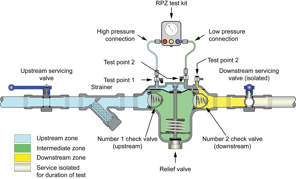
In addition to commissioning testing all RPZ valves require compliance testing. This is an onsite safety test to verify the valve is installed correctly and functioning satisfactorily.
Compliance testing shall be carried out at least annually or at more frequent intervals as specified by the water undertaker. The test due date is the date by which the next compliance test for a RPZ valve should be completed. Both test due date and compliance testing intervals are set by the water undertaker and cannot be changed without their consent.
To be considered as valid or ‘in test’ compliance testing of existing RPZ valves should be carried out no later than the test due date. In the case of RPZ valves tested annually compliance testing can be carried out no earlier than 30 days prior to the test due date. Early testing of other RPZ valves may be undertaken with the agreement of the water undertaker
Test intervals can only be changed with the agreement of the local water undertaker.
Please note whilst they may be willing to work with customers to accommodate practical consideration, such as shutdowns and aligning test due dates for RPZ valves on site it is unlikely, they will be willing to extend them.
For further information contact the local water undertaker.
The water undertaker may be willing to accept a valid compliance test report for testing carried out earlier than 30 days prior to the test due date, but this may result in the test due date for subsequent testing is brought forward.
For further information contact the local water undertaker.
Failure to comply with the requirements specified as a condition of consent may result in the water undertaker taking enforcement action which may include temporarily disconnecting the water supply to the premises and requiring the removal of the RPZ valve. Reconnection shall only be with the agreement of the water undertaker
Contact your local water undertaker immediately, the relevant contact details will also be in the conditions of consent letter.
Contact your local water undertaker immediately, the relevant contact details will also be in the conditions of consent letter.
RPZ valves should only be tested by those recognised by the local water undertaker as having sufficient knowledge, experience and skills to enable them to carry out on-site commissioning and/or compliance testing.
Unless recognised by the local water undertaker, on a site specific basis, to be considered as competent a tester must have a recognised qualification in RPZ valve commissioning and/or compliance testing, and should be a member of a recognised RPZ tester approved contractor scheme. They will need to be able to demonstrate to the satisfaction of the local water undertaker, their test equipment is suitably calibrated and they have appropriate liability insurance.
Mindful the person responsible for the RPZ valve has a legal obligation to ensure the valve is tested in accordance with the conditions of consent, the local water undertaker will consider this to be a matter between the RPZ tester and the organisation which engaged their services.
The commissioning and compliance testing of RPZ valves should only be undertaken by someone who is competent.
To be considered as competent by the local water undertaker RPZ testers must have a recognised qualification in RPZ valve commissioning and/or compliance testing from a recognised training provider.
Unless recognised on a site specific basis, they should be a member of a recognised RPZ tester approved contractor scheme and must be able to demonstrate their test equipment satisfies the minimum specification and also have appropriate liability insurance.

It is not compulsory to use someone who belongs to an approved contractor scheme to test RPZ valves. However, the local water undertaker has to be satisfied a tester is competent.
If the RPZ tester used is not a scheme member it is likely the local water undertaker will require further information before accepting the test report submitted by them as valid. For example, the tester will be likely to be asked to demonstrate:
They have satisfactorily completed a recognised qualification in RPZ valve commissioning and/or compliance testing from a recognised training provider
Their test equipment satisfies the minimum specification
They have appropriate liability insurance.
Yes, the RPZ AIM makes provision to recognise someone on a site specific basis. However, the local water undertaker has will have to be satisfied they are competent so will require further information before accepting the test report submitted by them as valid. For example, the company will be likely to be asked to demonstrate:
The tester has a qualification in RPZ valve commissioning and/or compliance testing recognised by the local water undertaker.
Their test equipment satisfies the minimum specification.
The company has appropriate liability insurance.
The water undertaker may also wish to witness the technician testing.
The easiest way to become recognised is to join an approved contractor RPZ sector scheme.
For further information contact your local water undertaker.
It is not compulsory for RPZ testers to join an approved contractor scheme. Joining a scheme will however mean that a tester will not be asked to demonstrate:
They have satisfactorily completed a qualification in RPZ valve commissioning and/or compliance testing recognised by the local water undertaker.
Their test equipment is calibrated by a pressure calibration service accredited by UKAS.
They have appropriate liability insurance.
There may be other advantages to scheme membership, please refer to your local scheme for further information.
Two of the ways, there may be others, to find a competent RPZ tester include searching the lists of those approved contractor schemes which have an RPZ tester sector, or the WaterSafe website www.watersafe.org.uk.
To locate a RPZ tester using the WaterSafe website search, select ‘RPZ valves testers’ from the service option and enter the postcode for the premises where the valve is located. The results generated will listed by distance from this location.

The RPZ AIM requires RPZ test kits to conform with a minimum specification, which includes being calibrated by a pressure calibration service accredited by UKAS. Please refer to the UKAS website for details of accredited organisations.
The accreditation schedule for the calibration organisation should include calibrating pressure differential measuring equipment in units of at least 1 kPa (or equivalent) or 0.5 kPa (or equivalent) as appropriate.
The RPZ test equipment should have an accuracy tolerance of: • Mechanical test equipment only of ±1.378 kPa (or equivalent) • Digital test equipment only ± 1 kPa (or equivalent)
Calibration certificates shall include details of the accuracy for differentials at 0.5 kPa (where appropriate), 7 kPa, 14 kPa and 34 kPa.
Test kits should be calibrated at least annually or, where specified by the kit manufacturer more frequently.
This is an on-site procedure to confirm a newly installed or repaired RPZ valve is installed and functioning in accordance with the requirements of the RPZ AIM
It is required by water undertakers before an RPZ valve can be brought into service. It applies to all newly installed RPZ valves and any valves which have been relocated, replaced, had components changed or RPZ valve installation which have been dismantled in anyway.
Full details are provided in section 5 of the RPZ AIM.
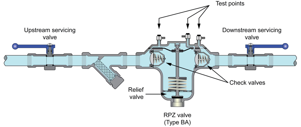
This is an on-site procedure to confirm a newly installed or repaired RPZ valve is installed and functioning in accordance with the requirements of the RPZ AIM.
It is required by water undertakers before an RPZ valve can be brought into service. It applies to all newly installed RPZ valves and any valves which have been relocated, replaced, had components changed or RPZ valve installation which have been dismantled in anyway.
Full details are provided in section 5 of the RPZ AIM.
This is an on-site procedure to demonstrate a RPZ valve has been installed correctly, and all key components are functioning as required under the RPZ AIM
In the case of existing RPZ valves the local water undertaker will advise when compliance testing is required. Those tested annually should not be tested earlier than 30 days prior to the test due date without the agreement of the water undertaker.
Full details are provided in section 5 of the RPZ AIM.
An on-site compliance test is required following commissioning testing and at set intervals thereafter.
In the case of existing RPZ valves the local water undertaker will advise when compliance testing is required. Those tested annually should not be tested earlier than 30 days prior to the test due date without the agreement of the water undertaker.
Full details are provided in section 5 of the RPZ AIM.
No, therefore it is important to use a water undertaker’s forms especially when submitting information electronically.
Details of the minimum information needed by a water undertaker in a test report is provided appendix 3 of the RPZ AIM. Please note that failure to provide the minimum level of information required may result in rejection.
Contact the local water undertaker for further information.
The minimum information required in a test report will be set out in a local water undertakers paperwork. This will include but not be limited to the following.
Information about the tester:
tester’s name
tester’s contact details including address, telephone number and email address
tester’s signature (water undertakers may accept electronic signatures)
tester’s scheme name and membership number
Information about premises at which the RPZ valve is located:
the address
telephone number
name and email address of the person responsible for the RPZ
Information about the installation including:
the location of the RPZ valve on site
a description of the water system which the RPZ valve forms part of including details of the type of equipment downstream of the RPZ valve.
confirmation that consent to install has been granted
confirmation that RPZ valve is installed in accordance with the conditions of consent
date of installation/commissioning
date of last test
Details relating to the RPZ valve including:
the name of the manufacturer
the model
the size
the serial number
Details relating to the testing including:
test due date
date of test
test results, including in the case of a test failure details of any observations made and action taken.
reason for test
Information about the test equipment used including:
the make of test kit o test kit serial number
calibration certificate
confirmation of its suitability for system being tested (e.g. hot water)
For further details contact the local water undertaker.
Before an RPZ valve can be brought into service the local water undertaker will require all newly installed RPZ valves, including replacement RPZ valves, satisfy both on-site commissioning and compliance testing, plus where required flushing and disinfection.
To be considered by the local water undertaker as being valid a test report must be:
Completed, signed and dated by a RPZ tester they consider to be competent using test equipment satisfying the minimum specification
Submitted in an acceptable format
Provide the minimum information required
Be received by the local water undertaker within 10 working days of test – unless the valve fails test in which case specific reporting requirements apply.
For further information please refer to the RPZ AIM.
Yes, a water undertaker can consider a test report to be invalid and decline to accept it.
To be considered by the local water undertaker as being valid a test report must be:
Completed, signed and dated by a RPZ tester they consider to be competent using test equipment satisfying the minimum specification
Submitted in an acceptable format
Provide the minimum information required
Be received by the local water undertaker within 10 working days of test – unless the valve fails test in which case specific reporting requirements apply.
For further information please refer to the RPZ AIM.
If a test report is not accepted by the local water undertaker, the valve is considered to be out of test and so should be retested as soon as possible. Please note the local water undertaker reserves the right to take enforcement action in such circumstances.
For further information contact the local water undertaker.
Unless there are exceptional circumstances, such as health and safety concerns, to help the local water undertaker to determine what action is required there is an expectation all testing will be completed.
If an RPZ valve fails compliance testing the next steps depend on whether the valve can be repaired and retested and how quickly this can be done.
If it is repaired and satisfactorily retested immediately then it may be returned to service. The test failure and successful retest, together with details of the repairs undertaken and any suspected contributing factors to the failure, will be reported by the RPZ tester to the water undertaker within 24 hours.
If the RPZ valve cannot be repaired and satisfactorily retested immediately, then the tester will notify the water undertaker straight away. The water undertaker will confirm what action is to be taken. The RPZ tester will notify you what action is required.
If an RPZ valve fails commissioning testing the RPZ tester has to notify the water undertaker within 24 hours. The valve itself will remain isolated until any action required by the water undertaker have been carried out. The RPZ tester will notify you what action is required.
Immediately contact the local water undertaker for further information.
The local water supplier will have confirmed what action should be taken when the RPZ tester notified them of the failure. The RPZ tester should have notified the person responsible for the valve or their representative what the local water undertaker wanted to happen.
If not or you have any further questions, contact the local water undertaker.
We use cookies to give you the best possible experience with Water Regs UK. Some are essential to provide website functions and ensure the website is secure. We also use cookies to help us understand how people use the site and to make improvements. Click "Accept All" to enable recommended settings or click "Manage cookies" to adjust your settings. For more details, see our Cookie Policy.